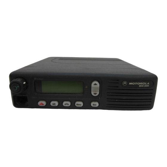
Motorola MCS 2000 Installation Manual
Hide thumbs
Also See for MCS 2000:
- User manual (323 pages) ,
- Service instructions manual (244 pages) ,
- Retrofit instructions (11 pages)
Table of Contents
Advertisement
This revision outlines changes that have occurred since the printing of your manual. Use this information to
supplement your manual.
REVISION CHANGE:
Page
Section No.
iv
1-2
1.2
2-2
2.2
2-3
2.6
5-2
5
6-4
6.2
© Motorola, Inc. 2003.
8000 W. Sunrise Blvd., Ft. Lauderdale, FL 33322
Printed in U. S. A.
Section Title
Table of Contents
Introduction: Siren/PA
Description
Operation: Public Address
Operation
Operation: External Radio
Operation
CPS Programming
Installation, Disassembly, and
Assembly: Horn-Ring
Transfer Relay
Paragraph
Description
2.6 and 6.2
Asterisk deleted from section headings.
Table 1-1
Asterisks deleted from rows 3 and 11 of
table 1-1.
Table 2-1
Replaced 'Wail' with 'Yelp' in Hi-Lo
Selected Tone row of table 2-1.
2.6
Deleted asterisk from section heading
and deleted first line of text.
Table 5.2
Deleted asterisk from Manual Tone cell
(row 2) and deleted table note.
6.2
Deleted asterisk from section heading
and deleted first line of text.
*FMR-2051-1*
MANUAL REVISION
6881096C46-O
MCS 2000 Mobile Radio
Installation Manual
FMR-2051-1
12/3/03
Advertisement
Table of Contents

Summary of Contents for Motorola MCS 2000
- Page 1 MANUAL REVISION 6881096C46-O MCS 2000 Mobile Radio Installation Manual This revision outlines changes that have occurred since the printing of your manual. Use this information to supplement your manual. REVISION CHANGE: Page Section No. Section Title Paragraph Description Table of Contents 2.6 and 6.2...
-
Page 2: Motorola,
This Page Intentionally Left Blank... -
Page 3: Table Of Contents
Table of Contents Foreword ....................F-ii Product Safety and RF Exposure Compliance ..................F-ii Manual Revisions ........................... F-ii Computer Software Copyrights ......................F-ii Document Copyrights ..........................F-ii Disclaimer............................... F-ii Trademarks ............................F-ii List of Figures ....................v List of Tables ....................vi Chapter 1 Introduction ................. - Page 4 Version Display in Test Mode ................... 7-2 Chapter 8 Siren/PA Schematics and Mechanical Drawings ..... 8-1 Appendix A Replacement Parts Ordering..........A-1 Basic Ordering Information ......................A-1 Motorola Online..........................A-1 Mail Orders ............................A-1 Telephone Orders ..........................A-2 Fax Orders .............................A-2 Parts Identification .........................A-2 Product Customer Service ......................A-2 Index ......................
-
Page 5: Chapter 1 Introduction
D A N G E R Siren P/A Description The MCS 2000 Siren/PA is an external accessory that generates siren tones and amplifies audio signals from the radio for public address (PA). It can deliver 65, 75, or 100 watts of siren power to an 11 ohm speaker, or 130 watts to dual 11 ohm speakers. -
Page 6: Table
Introduction: Siren P/A Description Some Siren/PA features can be programmed by a qualified radio technician using the Customer Programming Software (CPS). A summary of available features for each Siren/PA configuration is shown in Table 1-1. Table 1-1. Siren/PA Features Feature Using the Control Head Using the DEK-Plus Wail/Yelp/Hi-lo tones... -
Page 7: Chapter 2 Operation
Chapter 2 Operation Siren/PA Operation 2.1.1 Control Unit Depending on the installed configuration, the Siren/PA may be controlled by buttons on the control head or on the DEK-Plus. MCS 2000 MCS 2000 Wail Yelp HiLo ArHn Sirn MAEPF-27515-O Figure 2-1: Model III Control Head with Siren/PA Functions Siren Wail Yelp... -
Page 8: Public Address Operation
Operation: Public Address Operation Public Address Operation The Public Address feature amplifies and broadcasts the user's voice over the siren speaker. 2.2.1 Control Head/DEK-Plus To activate the Public Address function, momentarily press the PA button. The corresponding light- emitting diode (LED) will light up and the PA feature will be activated. The control head display will temporarily show the current PA volume setting. -
Page 9: External Radio Operation
SPKR SHORT. When the problem is corrected, the Siren/PA returns to its previous operation. In order for this feature to operate correctly, use only the following Motorola-approved speaker kits: TDN6251, TDN6252, TDN6253, and TDN6254. The use of any other... -
Page 10: Power-Up Feature
Operation: Power-Up Feature Power-Up Feature 2.8.1 Siren State The Siren/PA Accessory powers up in one of two ways: • Warm Start (battery power was not removed) • Cold Start (battery power was removed). 2.8.2 DEK-Plus In a Warm Start with a DEK-Plus, the Siren will power up with the PA Volume, the siren tone, and the Siren On/Off in their previously selected state at power-down, and with the PA off. -
Page 11: Chapter 5 Cps Programming
Chapter 5 CPS Programming The Customer Programming Software (CPS) stores programmed options in the radio’s codeplug. The CPS is preprogrammed with default settings at the factory, but it may be modified to suit your needs. There is one primary screen in the CPS for editing the Siren/PA options. To access this screen, double-click the “Radio Wide”... - Page 12 CPS Programming: The Siren/PA Options screen enables you to modify various Siren/PA options (default settings are indicated). The following tables describe the programmable fields and their settings: Table 5-1. Public Address Fields Field Options Options Audio Muting Disabled (default): Routes all audio to the Public Address speaker when in External Radio Mode.
-
Page 13: Chapter 6 Installation, Disassembly, And Assembly
6-2.) 9. (a) Control unit cable—for units using a DEK-Plus: • In the Dash Mount Configuration, the HKN6137 (MCS 2000, 4 ft. DEK-Plus) cable is used. • In the Remote Mount Configuration, the HKN6136 (MCS 2000, 17 ft. DEK-Plus) cable is needed. -
Page 14: Horn-Ring Transfer Relay
Installation, Disassembly, and Assembly: Horn-Ring Transfer Relay Horn-Ring Transfer Relay In order to make Siren operation more convenient under emergency conditions, the vehicle’s Horn- Ring (or buttons) can be used to control siren functions (refer to Chapter 2 on page 2-2).


