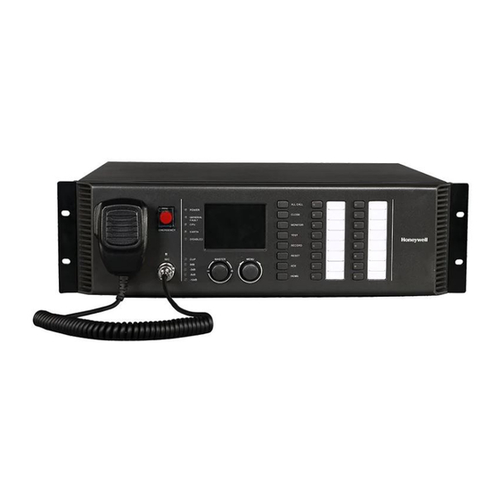
Summary of Contents for Honeywell RK-MCU
- Page 1 INTEVIO-Master Control Unit Product Instructions Model:RK-MCU M_2000061159_UL_1.1 M_2000060504_EN_1.0...
- Page 3 Precautions Danger This sign reminds users of “dangerous voltage” on the product. Caution This sign reminds users of important instructions attached to the product. In order to prevent electric shock, this equipment plug shall not be used as conductor to extend power supply Safety line.
-
Page 4: Important Safety Instructions
Ventilation To offset heat generated by the unit, it is necessary to provide ample ventilation around the unit. Avoid blocking or impeding the ventilation holes on the unit. To prevent unnecessary problems, install the unit in a place free from any vibrations, direct sunlight, humidity or dust circulation. Prevent liquids or other materials to enter cabinet If the unit gets wet or any foreign material enters the amplifier cabinet, immediately disconnect the AC power cord and consult your dealer or... -
Page 5: Network Security
Use only with the cart, stand, tripod, bracket or table specified by the manufacturer, or sold with the apparatus. When a cart is used, use caution when moving the cart/apparatus combination to avoid injury from tip-over. Unplug this apparatus during lightning storms or when unused for long periods of time. - Page 6 Password Precaution Please change the password during the system deployment. Users need to change the password regularly. The password with six numbers is preferred.
-
Page 7: Product Overview
Product Overview RK-MCU Master Control Unit is the central management device of the INTEVIO PA system, which is used to manage and monitor all devices and perform various operations. RK-MCU is integrated with audio storage, broadcast, zone control, monitor, timing control, and fault diagnosis. Built-in 500W digital power amplifier can drive a maximum 8 loudspeaker zones to meet requirements for small applications. -
Page 8: Function Introduction
Supports 3-wire and 4-wire volume controller. Capable to be integrated with the third party system through dry contact inputs. Zone expanders can be connected to increase the system capacity. Remote call stations can be connected for live broadcast and control. ... -
Page 9: Front Panel
Front Panel Button/Indicators Description The microphone bracket is used for PTT Microphone bracket microphone. A protective cover is above the emergency button to avoid wrong operation. Emergency button If switching to manual emergency mode, raise the protection cover, then press the button. -
Page 10: Rear Panel
Button/Indicators Description Wheel knob of Rotate left and right to navigate available menu menu options. Push in to select. Function buttons, including ALL, CLOSE, Function button MONITOR, TEST, RECORD, RESET, ACK, HOME, etc. Zone button & 8 zones/groups buttons with status indicator status indicator light lights, which can be configured as needed. - Page 11 Parts/Ports Description Output audio signal from microphone, able REC output to be connected to an external recording device. External audio source connection. AUX1/AUX2 Input connection for equipment, such as CD/DVD player, tuner, etc. External microphone or other audio device connection. MIC/LINE input The interface is balanced input.
- Page 12 Parts/Ports Description 8 dry contact output interfaces, which can Dry contact outputs be used to control external devices. 10 dry contact input interfaces, which can Dry contact inputs be connected to third party devices and used for business. Including the interfaces used to connect to the third party systems: ...
- Page 13 Parts/Ports Description 70V interface of 70V audio interface of external power external power amplifiers includes CH1B IN, CH2A IN, amplifier CH2B IN and the IN/OUT of spare amplifier. DIP switch to set the work mode of current MODE device and system. Calibration key To calibrate speaker line impedance.
-
Page 14: Technical Specifications
Technical Specifications Parameters Values Main power supply AC 100V-240V 50/60Hz Backup power supply 21.5V DC - 28.5V DC (Not recommended) Fuse T10AH 250V Power consumption <740W PTT Microphone Sensitivity -59±3dBV 100Hz -14KHz, ±3dB Frequency response 50dB, A-weighted Auxiliary input Number Input sensitivity 1V(0dBV) 10 KΩ... - Page 15 Parameters Values Output signal 1V (0dBV) <0.1% Internal Power Amplifier Max. power output 500W Output signal 70V(CH1A) 80Hz-18KHz, ±3dB Frequency response <0.1% Power Amplifier Interface Number 3 (CH1, CH2 and spare amplifier) Output signal 1.4V <0.1% Self-testing, amplifier fault and power saving Control signal control signal Loudspeaker Interface...
- Page 16 Parameters Values Others DC Power output 24V/1A Monitoring loudspeaker 2W/8Ω Ethernet interface 10M/100M Memory capacity 1GB Flash Memory, 8GB SD card Working Conditions 95%, without condensing Relative Humidity Operating temperature -10C~+45C(14F to +113F) Storage temperature -40C~+70C(-40F to +158F) Specification Dimension (W*H*D) 18.98 ×...
-
Page 17: Packing List
Packing List Components Qty. RK-MCU Labels Dry contact input terminals (3.81-10P) Dry contact output terminals (3.5-6P) System interface terminals (3.81-8P) Loudspeaker terminals (5.08-16P) Power amplifier terminals (5.08-2P) DC Power output terminal (5.08-2P) Backup power terminal (7.62-4P) Twisted-pair cable (2m) Audio cable... - Page 18 12 Clintonville Road, Northford, CT 06472, USA Tel: +1-800-323-4576 Manufacturer: Life Safety A/V (Guangzhou) Co., LTD No.257, Junye Road, Guangzhou GETDD, East 510530, China Tel: +86 (0)20 2839 9600 Fax: +86 (0)20 2820 8706 ©2017 Honeywell International Inc. All rights reserved.


