Sign In
Upload
Manuals
Brands
Canon Manuals
All in One Printer
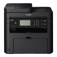
i-SENSYS MF211 Series
Canon i-SENSYS MF211 Series Manuals
Manuals and User Guides for Canon i-SENSYS MF211 Series. We have
1
Canon i-SENSYS MF211 Series manual available for free PDF download: Service Manual
Canon i-SENSYS MF211 Series Service Manual (308 pages)
Brand:
Canon
| Category:
All in One Printer
| Size: 26.14 MB
Table of Contents
Table of Contents
4
Safety Precautions
8
CDRH Provisions
9
Laser Safety
9
About Laser Beams
9
Handling Laser Scanner Unit
9
Toner Safety
10
About Toner
10
Handling Adhered Toner
10
Notes on Handling Lithium Battery
10
Notes on Assembly/Disassembly
10
1 Product Overview
11
Product Lineups
11
Main Unit
12
Options
12
Manufacture Sketch Drawing
13
Features
14
Product Specifications
14
Main Unit Specifications
14
Wireless LAN Specifications
16
SADF/DADF Specifications
16
FAX Specifications(FAX Model Only)
17
Name of Parts
18
External View
18
Cross Section
21
Control Panel
23
Touch Panel
23
Lcd Panel
24
2 Technical Overview
25
Basic Configuration
25
Configuration Function
26
Basic Sequence
26
Controller System
28
Main Controller
28
Engine Controller
28
Service Works
29
Document Exposure/Feeder System
30
Document Exposure System
30
Major Components
30
Document Feeder System
31
Original Detection
32
Jam Detection
33
Service Works
34
Laser Exposure System
35
Overview
35
Controlling the Laser Activation Timing
36
Laser Control
37
Laser Scanner Motor Control
37
Service Works
38
Image Formation System
39
Overview/Configuration
39
Print Process
39
Development Block
41
Transfer Block
41
High-Voltage Control
43
Generating Transfer Bias
43
Toner Cartridge
44
Toner Level Detection
44
Service Works
46
Fixing System
47
Overview/Configuration
47
Main Parts of Fixing Assembly
47
Various Control Mechanisms
48
Failure Detection
48
Fixing Temperature Control
48
Other Functions
49
Service Works
50
Pickup and Feeding System
51
Overview
51
Detecting Jams
52
Delay Jams
53
Delivery Delay Jam
53
Reversal Delay Jam
54
Delivery Stationary Jam
55
Pickup Stationary Jam
55
Stationary Jams
55
Other Jams
56
Service Works
57
External and Controls System
58
Power Supply
58
Service Works
59
3 Periodical Services
60
Periodically Replaced Parts
60
Consumables
60
Periodical Service
62
Scheduled Servicing
62
4 Disassembly/Assembly
63
List of Parts
63
External View
66
Front Side
68
Rear Side
68
List of Main Unit
69
DADF Unit and Reader Unit
69
SADF Unit and Reader Unit
70
Copyboard Unit and Reader Unit
70
Duplex Printer Unit
71
Sinplex Printer Unit
71
Electrical Components
72
Original Exposure/Feed System (DADF Model)
89
Layout Drawing
89
Removing the DADF Unit + Reader Unit
89
Disconnecting the DADF Unit + Reader Unit
92
Removing the DADF Pickup Unit
94
Removing the DADF Motor Unit
98
Removing the DADF Solenoid Unit
100
Removing the DADF Pickup Roller Unit
101
Removing the DADF Separation Pad
103
Removing the Copyboard Glass (DADF Model)
106
Removing the Contact Image Sensor (DADF Model)
108
Removing the Flat Bed Motor Unit (DADF Model)
110
Original Exposure/Feed System (SADF Model)
113
Layout Drawing
113
Removing the SADF Unit + Reader Unit
113
Disconnecting the SADF Unit and the Reader Unit
116
Removing the SADF Upper Cover Unit
118
Removing the SADF Pickup Unit
122
Removing the SADF Motor
123
Removing the SADF Pickup Roller Unit
124
Removing the SADF Separation Pad
127
Removing the Copyboard Glass (SADF Model)
130
Removing the Contact Image Sensor (SADF Model)
132
Removing the Flat Bed Motor Unit (SADF Model)
134
Original Exposure/Feed System (Copyboard Model)
137
Layout Drawing
137
Removing the Copyboard Cover
137
Removing the Copyboard Cover + Reader Unit
138
Removing the Copyboard Glass (Copyboard Model)
140
Removing the Contact Image Sensor (Copyboard Model)
142
Removing the Flat Bed Motor Unit (Copyboard Model)
144
External Cover/Internal System (Duplex Model)
147
Layout Drawing
147
Removing the Left Cover (Duplex Model)
148
Removing the Right Cover (Duplex Model)
149
Removing the Front Cover Unit (Duplex Model)
151
Removing the Upper Cover Unit (Duplex Model)
151
Removing the Duplex Feed Guide Unit. (Duplex Model)
153
Controller System (Duplex Model)
155
Layout Drawing
155
Removing the Control Panel Unit (Duplex Model)
155
Removing the Main Motor (Duplex Model)
157
Removing the Main Fan (Duplex Model)
159
Removing the Edge Left Cooling Fan (Duplex Model)
161
Removing the Edge Right Cooling Fan (Duplex Model)
163
Removing the Engine Controller PCB (Duplex Model)
164
Removing the Main Controller PCB (Duplex Model)
167
Removing the FAX NCU PCB (Fax Model 120V/230V) (Duplex Model)
169
Removing the Wirelss LAN PCB (Wifi Model + Duplex Model)
170
Removing the Paper Leading Edge Sensor PCB (Duplex Model)
170
Removing the Fixing Delivery/Paper Width Sensor PCB (Duplex Model)
173
Removing the Toner Sensor and Multi Pickup Sensor Unit (Fax Model + Duplex Model)
176
Removing the Speaker (Fax Model + Duplex Model)
178
Laser Exposure System (Duplex Model)
180
Layout Drawing
180
Removing the Laser Scanner Unit (Duplex Model)
180
Image Formation System (Duplex Model)
182
Layout Drawing
182
Removing the Transfer Roller (Duplex Model)
182
Fixing System (Duplex Model)
184
Layout Drawing
184
Removing the Fixing Assembly (Duplex Model)
184
Pickup Feed System (Duplex Model)
189
Layout Drawing
189
Removing the Pickup Unit (Duplex Model)
189
Removing the Pickup Tray Unit (Duplex Model)
194
Removing the Pickup Roller (Duplex Model)
196
Removing the Separation Pad (Duplex Model)
197
Removing the Delivery Slave Roller Unit (Duplex Model)
198
Removing the Pickup Solenoid (Duplex Model)
199
Removing the Duplex Solenoid (Duplex Model)
203
External Cover/Internal System (Simplex Model)
205
Layout Drawing
205
Removing the Left Cover (Simplex Model)
206
Removing the Right Cover (Simplex Model)
207
Removing the Front Cover Unit (Simplex Model)
209
Removing the Upper Cover (Simplex Model)
209
Removing the Rear Cover (Simplex Model)
211
Controller System (Simplex Model)
213
Layout Drawing
213
Removing the Control Panel Unit (Simplex Model)
213
Removing the Main Motor (Simplex Model)
215
Removing the Engine Controller PCB (Simplex Model)
217
Removing the Main Controller PCB (Simplex Model)
221
Removing the FAX NCU PCB (Fax Model 120V/230V + Simplex Model)
223
Removing the Wireless LAN PCB (Wifi Model + Simplex Model)
223
Removing the Paper Leading Edge Sensor (Simplex Model)
224
Removing the Fixing Delivery/Paper Width Sensor PCB (Simplex Model)
226
Removing the Toner Sensor and Multi Pickup Sensor Unit (Fax Model + Simplex Model)
229
Removing the Speaker (Fax Model + Simplex Model)
231
Laser Exposure System (Simplex Model)
233
Layout Drawing
233
Removing the Laser Scanner Unit (Simplex Model)
233
Image Formation System (Simplex Model)
235
Layout Drawing
235
Removing the Transfer Roller (Simplex Model)
235
Fixing System (Simplex Model)
237
Layout Drawing
237
Removing the Fixing Assembly (Simplex Model)
237
Pickup Feed System (Simplex Model)
242
Layout Drawing
242
Removing the Pickup Unit (Simplex Model)
242
Removing the Pickup Tray Unit (Simplex Model)
246
Removing the Pickup Roller (Simplex Model)
248
Removing the Separation Pad (Simplex Model)
249
Removing the Delivery Slave Roller Unit (Simplex Model)
250
Removing the Pickup Solenoid (Simplex Model)
252
5 Adjustment
255
Mechanical Adjustment
255
Confirming Nip Width
256
6 Trouble Shooting
257
Test Print
257
Test Print Function
258
Trouble Shooting Items
259
Image Faults
259
Paper Creases
262
Paper Curls
262
Log Collector
264
Outline
264
Troubleshooting
265
Version Upgrade
266
Overview
266
Ust
266
Preparation
266
System Requirements
266
Downloading System Software
267
Upgrading Via Internet
269
7 Error Codes Overview
271
Error Codes
272
Jam Codes
273
8 Service Mode
274
Overview
274
Entering Service Mode
275
Service Mode Menu
275
Copier
277
Display
277
I/O
278
Adjust
278
Function
279
Counter
282
Feeder
284
Adjust
284
Function
284
Fax
285
List of SSSW
285
List of MENU
287
List of NUM
288
List of NCU
289
Dial Tone
289
Testmode
293
System
293
Scan
293
Fax
294
Panel
295
Network
296
Sssw
296
Appendix
297
Service Tools
297
Solvent/Oil List
297
General Circuit Diagram (Duplex Model)
297
General Circuit Diagram (Simplex Model)
297
General Timing Chart
297
List of User Mode
297
Network Settings
303
Preferences
304
Quiet Mode Time
305
Common Settings
305
Copy Settings
305
Fax Settings
305
Scan Settings
306
Printer Settings
306
Adjustment/Maintenance
306
System Management Settings
306
Backup Data
308
Advertisement
Advertisement
Related Products
Canon i-SENSYS MF4350d
Canon I-sensys mf4370dn
Canon i-SENSYS MF3010
Canon i-SENSYS MF229dw
Canon i-SENSYS MF216n
Canon i-SENSYS MF212w
Canon i-SENSYS MF4140
Canon imageCLASSMF5700 Series
Canon imageRUNNER 2800 Series
Canon imageRUNNER ADVANCE 8500 series
Canon Categories
Printer
Digital Camera
All in One Printer
Camcorder
Scanner
More Canon Manuals
Login
Sign In
OR
Sign in with Facebook
Sign in with Google
Upload manual
Upload from disk
Upload from URL