Sign In
Upload
Manuals
Brands
Canon Manuals
Printer
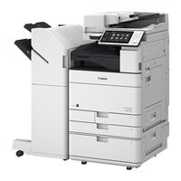
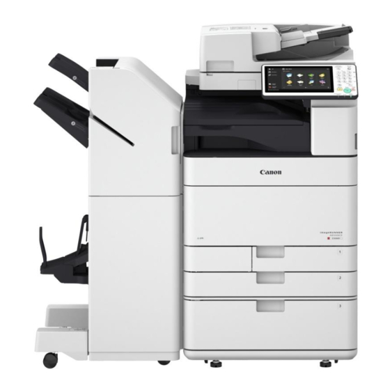
imageRUNNER ADVANCE C5560
Canon imageRUNNER ADVANCE C5560 Manuals
Manuals and User Guides for Canon imageRUNNER ADVANCE C5560. We have
4
Canon imageRUNNER ADVANCE C5560 manuals available for free PDF download: Service Manual, Configuration And Installation Manual, Troubleshooting Manual
Canon imageRUNNER ADVANCE C5560 Service Manual (1331 pages)
Brand:
Canon
| Category:
Printer
| Size: 88.12 MB
Table of Contents
Table of Contents
4
Safety Precautions
15
Laser Safety
16
Handling of Laser System
16
Turn Power Switch on
16
Power Supply
17
Toner Safety
17
About Toner
17
Handling Adhered Toner
17
Notes When Handling a Lithium Battery
17
Notes before It Works Serving
18
Points to Note at Cleaning
18
Notes on Assembly/Disassembly
18
1 Product Overview
19
Product Lineup
20
Host Machine
20
Options
21
Features
25
Product Features
25
Toner Container
25
Setup Guide
26
Introduction of Situation Mode
26
Limiting of Color Printing
27
Specifications
29
Product Specifications
29
Weight and Size
31
Productivity
31
Paper Type
31
Parts Name
40
External View
40
Cross Section View
45
Control Panel
46
2 Technology
47
Basic Configuration
48
Functional Configuration
48
Original Exposure System
49
Overview
49
Magnification Ratio
57
Original Size Detection
57
Dust Detection Control
58
Image Processing
59
Color Displacement Correction Processing in Vertical Scanning Direction
62
Outline of Electric Circuits
62
Scanner Unit
65
Pickup Feed System
66
Fan
73
Power Supply Assembly
74
Controller System
75
Specifications / Configuration
75
Motion Sensor
78
Shutdown Sequence
79
Startup Sequence
80
Laser Exposure System
81
Overview
81
Laser ON/OFF Control
83
Horizontal Scanning Synchronization Control
83
Vertical Scanning Synchronization Control
84
APC (Auto Power Control)
85
Laser Scanner Motor Control
85
BD Correction Control
86
Laser Shutter Control
87
Image Skew Correction Control
88
Image Formation System
89
Overview
89
Charging Control
91
Developing Control
96
Primary Transfer Control
97
Secondary Transfer Control
102
Pre-Exposure Control
109
Image Stabilization Control
110
Toner Supply Control
116
Waste Toner Feed Control
127
Other Controls
129
Fixing System
132
Overview
132
Overview of Fixing Temperature Control
134
Standby Temperature Control
135
Print Temperature Control
136
Down Sequence Control
137
Fixing Film Edge Cooling Control
139
Film Unit Engagement/Disengagement Control
139
Fixing Unit Detection
140
Detection of New Fixing Film Unit
141
Protection Function
141
Pickup Feed System
143
Overview
143
Cassette Pickup Assembly
149
Multi-Purpose Tray Pickup Assembly
156
Fixing/Registration Assembly
158
Duplex / Delivery Assembly
161
Jam Detection
162
External Auxiliary System
164
Counter Control
164
Fan Control
166
Environment Heater Control
168
Power Supply
169
Power-Saving Function
170
Quick Startup
173
3 Periodical Service
175
Consumable Parts List
176
Host Machine
176
Cassette Feeding Unit-AM1
179
High Capacity Cassette Feeding Unit-A1
180
Paper Deck Unit-F1
180
Booklet Finisher-Y1
181
Staple Finisher-Y1
181
Inner Finisher-H1
181
Cleaning/Check/Adjustment Locations
183
Compatibility of Consumable Parts
185
4 Disassembly/Assembly
186
Preface
187
Outline
187
List of Parts
188
List of Cover
188
List of Electrical Parts
193
List of Connectors
215
Original Exposure System
238
Removing the ADF Pre-Separation Unit / ADF Separation Roller
238
Removing the ADF Pickup Roller Unit
239
Removing the ADF Pickup Roller and the ADF Feed Roller
240
Installing the ADF Pickup Roller Unit
242
Removing the ADF
244
Installing the White Plate
245
Removing the ADF Scanner Unit
247
Cleaning the Paper Back Reading Glass
250
Removing the Rear Cover
251
Cleaning the Lead Roller 1/2/3
252
Removing the ADF Driver PCB
256
Removing the Reader Controller PCB
257
Cleaning the Reader Scanner Unit Scanner Mirror
259
Removing the Reader Scanner Unit
262
Main Controller System
266
Removing the HDD
266
Removing the Main Controller PCB
267
Removing the Riser PCB
269
Opening the Controller Box
272
Removing the DC Controller PCB
273
Removing the Primary Transfer/Bk Developing Charging High-Voltage Unit
275
Removing the Rear Lower Cover
276
Removing the Power Supply Unit (12 V/24 V)
277
Removing the Feed/Drum Driver PCB
278
Removing the Relay PCB
279
Removing the Secondary Transfer High Voltage Unit
280
Removing the AC Driver PCB
282
Removing the Control Panel
283
Removing the All-Night Power Supply PCB
288
Removing the Developing High-Voltage PCB (Ymc)/Charging High-Voltage PCB (YMC)
289
Laser Control System
292
Cleaning the Dustproof Glass
292
Removing the Dustproof Glass Cleaning Pad
293
Removing the Laser Scanner Unit
293
Image Formation System
297
Removing the Toner Filter
297
Removing the ITB Unit
297
Cleaning the Registration Patch Sensor
301
Removing the Registration Patch Sensor (Front), (Middle), (Rear)
302
Removing the ITB Cleaning Unit
304
Removing the ITB Cleaning Blade Unit
306
Installing the ITB Cleaning Blade Unit
307
Removing the ITB
309
Removing the Primary Transfer Roller (Bk)
313
Removing the Primary Transfer Roller (C, M, Y)
317
Removing the Secondary Transfer Inner Roller
321
Installing the ITB
323
Removing the Waste Toner Container
331
Pulling out the Process Unit
331
Removing the Process Unit
334
Installing the Process Unit
335
Removing the Drum Unit
339
Installing the Drum Unit
340
Removing the Developing Unit
342
Installing a New Developing Unit
345
Removing the Waste Toner Feed Unit
347
Removing the Secondary Transfer Roller/Secondary Transfer Separation Guide Unit
351
Installing the Secondary Transfer Roller/Secondary Transfer Separation Guide Unit
353
Removing the Main Drive Unit
355
Removing the Toner Container Front Inner Cover
360
Removing the Hopper Unit (M)
363
Removing the Hopper Unit (Y)
365
Removing the Hopper Unit (C)
368
Removing the Hopper Unit (Bk)
371
Fixing System
374
Removing the Fixing Unit
374
Removing the Film Unit
375
Cleaning the Fixing Shutter Cover
379
Cleaning the Fixing Separation Guide
380
Cleaning the Fixing Inlet Guide
381
Removing the Pressure Roller and Pressure Roller Bearing
382
Removing the 27T Gear
384
Pickup Feed System
386
Cleaning the Secondary Transfer Guide
386
Cleaning the Feed Contact Guide
387
Cleaning the Registration Roller
387
Cleaning the Pre-Registration Guide Unit
388
Cleaning the Registration Sensor
389
Cleaning the Between-Cassette 1/2 Sensor
390
Cleaning the Fixing Delivery Guide
392
Cleaning the Fixing Rear Roller
393
Cleaning the Fixing Delivery Roller
394
Removing the Duplex Feed Upper Rollers
395
Removing the Duplex Feed Lower Roller
396
Cleaning the Second/Third Delivery Roller, Roller and First, Second, and Third Delivery Rollers
397
Removing the Right Rear Cover 1
399
Removing the Front Right Cover
401
Removing the Reverse Backend Guide and Inner Output Cover
402
Removing the Second/Third Delivery Unit
402
Removing the First Delivery Unit
404
Removing the Duplex Unit
407
Removing the Multi-Purpose Tray/Feed/Separation Roller
408
Removing the Pickup/Delivery/Separation Roller (Cassette 1/2)
411
Removing the Right Door
412
Removing the Cassette 1/2 Pickup Unit
415
Removing the Transparency Sensor/Registration Sensor
417
5 Adjustment
420
Pickup Feed System
421
Image Position Adjustment
421
Geometric Characteristics Adjustment
424
Original Exposure System
429
Reader Assembly
429
Adf
430
Actions at Parts Replacement
442
MP Pickup Tray Unit
442
DC Controller PCB
442
Control Panel CPU PCB
443
Hard Disk
444
Laser Scanner Unit
446
ITB Unit
447
Itb
447
Secondary Transfer Inner Roller
447
Secondary Transfer Roller
449
Drum Unit
450
Developing Unit
450
Patch Sensor
450
Reader Controller PCB
450
Scanner Unit (Paper Front)
452
Scanner Unit (Paper Back)
452
Copyboard Glass
453
6 Troubleshooting
454
Initial Check
455
Test Print
456
Overview
456
How to Use the Test Print
457
Troubleshooting Items
461
Fixing Wrinkle/Jams Caused by Deterioration in the Rib of the Fixing Inlet Guide
461
Display of "Non-Canon Product" Message
462
Forcible Stop of Paper Feed
463
Controller Self Diagnosis
466
Preface
466
Overview
466
Basic Flowchart
468
Boot Method
469
Diagnosis Result
469
Limitations
472
Debug Log
473
Overview
473
Saving to a USB Device Using Download Mode (Method 1)
477
Saving to a USB Device with Counter Key + Numeric Key (Methods 2 and 4)
478
Saving to a PC Using SST (Method 3)
479
Saving to a USB Flash Drive Using Service Mode (Method 5)
482
Service Mode Relating to Debug Logs
482
Collecting the Log of Key Operations
485
Network Packet Capture
486
7 Error/Jam/Alarm
494
Overview
495
Location Code
495
Pickup Position Code
495
Pickup Size
495
Points to Note When Clearing MN-CON
497
Points to Note When Clearing HDD
497
Error Code
498
Error Code Details
498
Jam Code
643
Jam Type
643
Jam Screen Display Specification
643
Main Unit
644
ADF/ Reader
646
Cassette Feeding Unit-AM1
648
High Capacity Cassette Feeding Unit-A1
649
Paper Deck Unit-F1
650
Inner Finisher-H1
651
Staple Finisher-Y1/ Booklet Finisher-Y1
652
2/4 Hole Puncher Unit-A1
653
Inner 2/4 Hole Puncher-B1
654
Buffer Pass Unit-L1
655
Alarm Code
656
Alarm Code Details
656
8 Service Mode
672
Overview
673
Points to Note When Executing Service Mode
673
Service Mode Menu
673
Description of Service Mode Items
673
Operation Check of Electrical Components
674
Enhanced I/O Information
677
Security Support
679
Switching the Screen Display (Level 1 <->2)
680
Service Mode Backup
680
Output of Service Print Data
681
SITUATION Mode
686
Function to Mask the Screen During Remote Access
686
Copier
689
Display
689
I/O
781
Adjust
800
Function
881
Test
1047
Counter
1054
Feeder
1084
Display
1084
Adjust
1084
Function
1086
Sorter
1089
Adjust
1089
Function
1100
Board
1110
9 Installation
1111
How to Check this Installation Procedure
1113
Symbols
1113
Points to Note at Installation
1114
Checking before Installation
1115
Checking Power Supply
1115
Checking the Installation Environment
1115
Checking the Installation Space
1115
Points to Note before Installation
1115
Combination Table of Accessory Installation
1117
Unpacking
1118
Checking the Contents
1119
Installation Procedure
1120
Removing the Packaging Materials
1120
Installing the Scanner
1123
Installing the Drum Unit
1123
Setting the Environment Heater Switch
1131
Installing IC Card Reader (EUR Only)
1131
Setting the Cassette
1137
Advertisement
Canon imageRUNNER ADVANCE C5560 Configuration And Installation Manual (67 pages)
Brand:
Canon
| Category:
Printer
| Size: 4.56 MB
Table of Contents
Table of Contents
3
Chapter 1: Introduction
4
Chapter 2: Preparing the Device Being Removed
6
Chapter 3: Imagerunner ADVANCE C5560 Machine Configuration
8
Chapter 4: Configuring Device Settings
9
Chapter 5: Center IP / Subnet Mask / Gateway
18
Chapter 6: Imagepass-P1 Set-Up
19
Chapter 7: Performing Calibration
43
Chapter 8: Configuring Network Scanning
47
Chapter 9: Print Driver Installation on Workstation Using the PUMA Application
51
Chapter 10: COM Test Verification
55
Chapter 11: Quality Validation Process
56
Chapter 12: Post Installation Actions
59
Appendix
61
Imagerunner ADVANCE C5560 Post Installation Checklist
61
Certification of Canon Machine Hard Disk Drive Erase
61
Canon imageRUNNER ADVANCE C5560 Troubleshooting Manual (25 pages)
Brand:
Canon
| Category:
All in One Printer
| Size: 7.49 MB
Table of Contents
Table of Contents
3
Image Faults
4
Image Displacement When Using ADF Due to Broken Grounding Sheet
4
Horizontal White Line Appears at 120Mm from the Leading Edge of the Sheet with a Bk Halftone Image
5
Horizontal Lines with 94Mm Pitch on a Halftone Image
6
Image Failure Occurring Repeatedly at the same Interval (XX Pitch)
7
Faulty Feeding
9
Poor Stacking/Wrinkles/Tear of Paper Due to Inappropriate Position of the Aligning Plate of the Processing Tray Unit (Inner Finisher-G1/H1)
9
Malfunction
12
Toner Leakage from the Bottom of the Process Unit Due to the Spring in the Shutter Coming off
12
Insert the Toner Container" Is Displayed Caused by Half-Insertion of the Front Door SW Connectors
13
Points to Note When Installing the Rail Unit (Inner Finisher-H1)
17
Jam (Delivery Options)
18
0211/0212/110A Jam Code Caused by Disengaged Timing Belt (Buffer Pass Unit)
18
Error Code
22
E583-8001/E583-8002 Due to Malfunction of the Front/Rear Tray Auxiliary Guides(Staple/Booklet Finisher_Y1)
22
Advertisement
Canon imageRUNNER ADVANCE C5560 Troubleshooting Manual (27 pages)
Brand:
Canon
| Category:
All in One Printer
| Size: 1.93 MB
Table of Contents
Table of Contents
3
Malfunction
4
Misdetection of Document Size Due to Dirt on the Copyboard Glass
5
Measures to Prevent Abnormal Noise in the Fixing Assembly
8
Jam Code
9
Measure to Prevent 010A/020A Jams
10
Error Code
15
Points to Note When Opening the Package of Inner Puncher (Inner Puncher)
16
Image Quality
17
Measure to Prevent Image Streaking on Paper Width of 305Mm (12 Inches) or Larger
18
Specifications-Related
25
Points to Note When Attaching Tension Spring of the Buffer/Saddle Inlet Flapper(Staple Finisher-V1/V2/Y1/AA1 Booklet Finisher-V1/V2/Y1/AA1)
26
Advertisement
Related Products
Canon imageRUNNER ADVANCE C5560i III
Canon imageRUNNER ADVANCE C5550i III
Canon imageRUNNER ADVANCE C5540i III
Canon imageRUNNER ADVANCE C5535i III
Canon imageRUNNER ADVANCE C5550
Canon imageRUNNER ADVANCE C5540
Canon imageRUNNER ADVANCE C551
Canon C5500 Series
Canon imageRUNNER ADVANCE C55A0i
Canon imageRUNNER ADVANCE DX C568iFZ
Canon Categories
Printer
Digital Camera
All in One Printer
Camcorder
Scanner
More Canon Manuals
Login
Sign In
OR
Sign in with Facebook
Sign in with Google
Upload manual
Upload from disk
Upload from URL