Sign In
Upload
Manuals
Brands
GE Manuals
Single board computers
IMP2B
GE IMP2B Manuals
Manuals and User Guides for GE IMP2B. We have
1
GE IMP2B manual available for free PDF download: Hardware Reference Manual
GE IMP2B Hardware Reference Manual (55 pages)
Brand:
GE
| Category:
Single board computers
| Size: 2.37 MB
Table of Contents
Table of Contents
4
1 Overview
8
Features
8
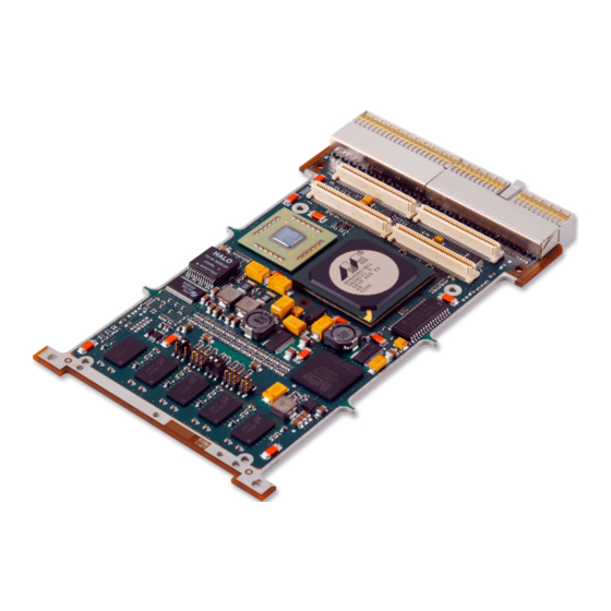
Figure 1-1 View of IMP2B
9
2 Configuration
10
Link Functions
10
Table 2-1 Link Functions
10
Figure 2-1 Link Positions (Top)
10
Suggested Link Settings
11
Factory Test Link (P1)
11
Flash Boot Image Select Links (P2 1-2 and 3-4)
11
Table 2-2 Suggested Link Settings
11
Table 2-3 Links P2 1-2 and 3-4
11
Backplane Flash Programming Link (P2 5-6)
12
Flash Protection Password Unlock Link (P3 1-2)
12
Table 2-4 Link P2 5-6
12
Table 2-5 Link P3 1-2
12
Boot Flash Write Enable Link (P3 3-4) and User Flash Write Enable Link (P3 5-6)
13
JTAG Scanbridge Enable Link (P4 1-2)
13
Table 2-6 Links P3 3-4 and 5-6
13
Table 2-7 Link P4 1-2
13
Backplane JTAG Buffer Enable Link (P4 3-4)
14
Backplane JTAG Auto-Write Enable Link (P4 5-6)
14
Force 33 Mhz Operation Link (P5 1-2)
14
Table 2-8 Link P4 3-4
14
Table 2-9 Link P4 5-6
14
Table 2-10 Link P5 1-2
14
Nvram/Serial EEPROM Write Enable Link (P5 3-4)
15
Spare Link (P5 5-6)
15
Special Linking Requirements
15
Table 2-11 Link P5 3-4
15
3 Functional Description
16
Powerpc Processor
16
Figure 3-1 Block Diagram
16
Host Bridge
17
Ram
18
Non-Volatile RAM (NVRAM)
18
Table 3-1 SDRAM Options
18
Flash Memory
19
Boot Flash
19
Table 3-2 Flash Options
19
Table 3-3 Boot Image Selection
19
User Flash
20
Flash Sector Protection
20
Memory Map Set up by Vxworks (as Seen by CPU)
21
PMC Site
21
Table 3-4 Vxworks Card-Level Memory Map
21
Table 3-5 PMC Site IDSEL Connections
21
Limited Host, Full PMC User I/O' Mode
22
Peripheral Only' Mode
22
PMC Rear I/O Tracking
22
Alternative PMC I/O' Mode
23
Table 3-6 Alternative PMC I/O Mode Signals
23
Serial Ports
24
Table 3-7 Signal Sets Per Port in Available Modes
24
Figure 3-2 RS422/485 Signal Definition
24
Ethernet
25
Usb 2.0
25
Timers
25
Watchdog Timer
25
DMA Engines
26
I 2 C Interface
26
Serial EEPROM
26
Real-Time Clock
26
Table 3-8 I 2 C Device Addresses
26
Elapsed Time Indicator
27
Temperature Sensing
27
Epld
28
Internal EPLD Registers
28
Table 3-9 EPLD Registers
28
Board ID Register 1 - Offset 0X00000000
29
Board ID Register 2 - Offset 0X00000002
29
Device/Bus Information Register 1 - Offset 0X00000004
29
Table 3-10 Board ID Register 1
29
Table 3-11 Board ID Register 2
29
Table 3-12 Device/Bus Information Register 1
29
Device/Bus Information Register 2 - Offset 0X00000006
30
Configuration Register 1 - Offset 0X00000008
30
Table 3-13 Device/Bus Information Register 2
30
Table 3-14 Configuration Register 1
30
Configuration Register 2 - Offset 0X0000000A
31
Control Register 1 - Offset 0X0000000C
31
Table 3-15 Configuration Register 2
31
Table 3-16 Control Register 1
31
Control Register 2 - Offset 0X0000000E
32
Test Registers
32
Scratchpad Registers
32
Table 3-17 Control Register 2
32
Table 3-18 Test Registers
32
Table 3-19 Scratchpad Registers
32
EPLD Interrupt Register - Offset 0X00000020
33
Software Reset Register - Offset 0X00000040
33
Table 3-20 EPLD Interrupt Register
33
Table 3-21 Software Reset Register
33
Semaphore Register - Offset 0X00000060
34
General Purpose I/O Controller
34
Table 3-22 Semaphore Register
34
GPIO Data Register - Offset 0X00000402
35
GPIO Direction Control Register - Offset 0X00000400
35
GPIO Interrupt Mode Register - Offset 0X00000406
35
GPIO Polarity Control Register - Offset 0X00000404
35
Table 3-23 GPIO Line to Register Bit Mapping
35
GPIO Interrupt Active Register - Offset 0X00000408
36
GPIO Interrupt Enable Register - Offset 0X0000040A
36
GPIO Masked Interrupt Status Register - Offset 0X0000040C
36
Compactpci Arbiter
36
Resets
37
Table 3-24 Reset Causes
37
Interrupts
38
Table 3-25 Interrupt Mapping
38
Table 3-26 Interrupt Combination
38
Jtag
39
Table 3-27 JTAG Chains
39
Leds
40
Table 3-28 Leds
40
Figure 3-3 LED Positions
40
Front Panel
41
Table 3-29 BIT Status Leds
41
Figure 3-4 Front Panel
41
4 Connectors
42
Table 4-1 Connector Functionality
42
Figure 4-1 Connector Positions
42
J2 Connector Pinout
43
System Controller Card (IMP2B-Xxxxa)
43
Table 4-2 J2 Pinout (System Controller)
43
Peripheral Only Card (IMP2B-Xxxxb)
44
Table 4-3 J2 Pinout (Peripheral Only)
44
Limited Host, Full PMC User I/O Card (IMP2B-XXXXD)
45
Table 4-4 J2 Pinout (Limited Host, Full PMC User I/O)
45
System Controller Card - Alternative PMC I/O (IMP2B-Xxxxe)
46
Table 4-5 J2 Pinout (System Controller- Alternative PMC I/O)
46
J2 Connector Signal Descriptions
47
PMC Rear I/O Tracking
47
JTAG Test Header (P38)
47
Table 4-6 J2 Signal Descriptions
47
A • Specifications
48
Technical Specification
48
Table A-1 Technical Specification
48
Electrical Specification
49
Table A-2 Voltage Supply Requirements
49
Table A-3 Power Dissipation
49
Weight
50
Reliability (MTBF)
50
Table A-4 Reliability (MTBF)
50
Product Codes
51
Software Support
51
Table A-5 Product Codes
51
Development Tools
52
I/O Modules
52
Index
53
Advertisement
Advertisement
Related Products
GE IM-4A
GE IM4D
GE IM4LED
GE IM-5SS
GE IM4
GE IM6
GE IM-5D
GE Moisture Image 1 Series
GE IM-6D
GE imagine
GE Categories
Refrigerator
Ranges
Microwave Oven
Air Conditioner
Dishwasher
More GE Manuals
Login
Sign In
OR
Sign in with Facebook
Sign in with Google
Upload manual
Upload from disk
Upload from URL