Sign In
Upload
Manuals
Brands
HP Manuals
Measuring Instruments
HP 8712ET
User Manuals: HP HP 8712ET RF Network Analyzer
Manuals and User Guides for HP HP 8712ET RF Network Analyzer. We have
6
HP HP 8712ET RF Network Analyzer manuals available for free PDF download: User Manual, User Manual Supplement, Installation Note, Quick Start Manual
HP HP 8712ET User Manual (480 pages)
RF Network Analyzers
Brand:
HP
| Category:
Measuring Instruments
| Size: 3.96 MB
Table of Contents
Table of Contents
9
1 Installing the Analyzer
17
Introduction
18
Step 1. Check the Shipment
19
Step 2. Meet Electrical and Environmental Requirements
20
Step 3. Check the Analyzer Operation
25
Step 4. Configure the Analyzer
26
Connecting Peripherals and Controllers
27
Installing the Analyzer in a Rack
32
Preventive Maintenance
33
Clean the CRT
33
Check the RF Front Panel Connectors
33
2 Getting Started
35
Introduction
36
Front Panel Tour
37
Entering Measurement Parameters
38
Entering Frequency Range
40
Entering Source Power Level
40
Scaling the Measurement Trace
40
Entering Active Measurement Channel and Measurement Type
41
Viewing Measurement Channels
42
Performing the Operator's Check
44
Equipment List
44
Make a Transmission Measurement
45
Make a Broadband Power Measurement
47
Make a Reflection Measurement
48
If the Analyzer Fails the Operator's Check
51
3 Making Measurements
53
Introduction
54
Measuring Devices with Your Network Analyzer
55
Attenuation and Amplification in a Measurement Setup
59
When to Change the System Impedance
60
The Typical Measurement Sequence
61
Using the BEGIN Key to Make Measurements
62
BEGIN Key Overview
63
Using the BEGIN Key to Configure Measurements
64
AUTOST Files
66
The User BEGIN Function
66
Measuring Transmission Response
67
Enter the Measurement Parameters
67
Perform an Enhanced Response Calibration
68
Measuring Reflection Response
84
Enter the Measurement Parameters
84
Perform a One-Port Reflection Calibration
85
Connect the DUT
87
View and Interpret the Reflection Measurement Results
89
Making a Power Measurement Using Broadband Detection
91
Enter the Measurement Parameters
92
Perform a Normalization Calibration
93
Connect the DUT
94
View and Interpret the Power Measurement Results
95
Measuring Conversion Loss
97
Enter the Measurement Parameters
98
Perform a Normalization Calibration
98
Connect the DUT
100
View and Interpret the Conversion Loss Results
101
Making Measurements with the Auxiliary Input
103
Auxiliary Input Characteristics
104
Measuring Group Delay
105
Enter the Measurement Parameters
106
Perform an Enhanced Response Calibration
106
Connect the DUT
107
View and Interpret the Group Delay Measurement Results
107
Measuring Impedance Using the Smith Chart
109
Enter the Measurement Parameters
109
Perform a One-Port Reflection Calibration
110
Connect the DUT
110
View and Interpret the Impedance Measurement Results
111
Measuring Impedance Magnitude
115
How the Reflection Measurement Works
115
How the Transmission Measurement Works
116
4 Using Instrument Functions
119
Introduction
120
Using Markers
121
To Activate Markers
123
To Turn Markers off
123
To Use Marker Search Functions
124
To Use Marker Math Functions
136
To Use Delta (∆) Marker Mode
142
To Use Other Marker Functions
144
To Use Polar Format Markers
145
To Use Smith Chart Markers
145
Using Limit Testing
146
To Create a Flat Limit Line
147
To Create a Sloping Limit Line
148
To Create a Single Point Limit
150
To Use Marker Limit Functions
150
To Use Relative Limits
154
Other Limit Line Functions
155
Additional Notes on Limit Testing
157
Using Reference Tracking
160
To Track the Peak Point
161
To Track a Frequency
162
Customizing the Display
163
Using the Split Display Feature
164
Enabling/Disabling Display Features
165
Modifying Display Annotation
166
Expanding the Displayed Measurement
170
Saving and Recalling Measurement Results
173
Saving Instrument Data
175
To Recall from a Floppy Disk or Internal Memory
178
Other File Utilities
181
To Use Directory Utilities
183
Formatting a Floppy Disk
184
Connecting and Configuring Printers and Plotters
185
Select a Compatible Plotter or Printer
185
Select an Appropriate Interface Cable
185
Connect the Printer or Plotter
187
Configure the Hardcopy Port
188
Define the Printer or Plotter Settings
190
Printing and Plotting Measurement Results
195
To Select the Copy Port
195
To Define the Output
196
Using a Keyboard
200
To Connect the Keyboard
200
To Use the Keyboard to Edit
200
Front Panel Control Using a Keyboard
201
Using an External VGA Monitor
204
Customizing Color on an External Monitor
204
Synchronizing and Positioning the Display
206
5 Optimizing Measurements
207
Introduction
208
Increasing Sweep Speed
209
To Increase the Start Frequency
209
To Set the Sweep Time to AUTO Mode
210
To Widen the System Bandwidth
210
To Reduce the Amount of Averaging
211
To Reduce the Number of Measurement Points
211
To View a Single Measurement Channel
212
To Turn off Alternate Sweep
213
To Turn off Markers and Marker Tracking
213
To Turn off Spur Avoidance
214
To Avoid Frequency Bandcrossings (HP 8714ET Only)
214
Increasing Network Analyzer Dynamic Range
215
To Increase the Receiver Input Power
215
To Reduce the Receiver Noise Floor
216
Reducing Trace Noise
218
To Activate Averaging for Reducing Trace Noise
218
To Change System Bandwidth for Reducing Trace Noise
218
To Eliminate Receiver Spurious Responses
219
Reducing Mismatch Errors
221
Reducing Mismatch Errors in a Reflection Measurement
221
Reducing Mismatch Errors in a Transmission Measurement
222
Reducing Mismatch Errors When Measuring both Reflection and Transmission
222
Compensating for Phase Shift in Measurement Setups
223
Port Extensions
223
Electrical Delay
224
Measuring Devices with Long Electrical Delay
225
6 Calibrating for Increased Measurement Accuracy
227
Introduction
228
Measurement Calibration Overview
228
The Calibration Reference Plane
231
Default Versus User-Defined Calibration
232
When to Use a Default Calibration
232
When to Perform a User-Defined Calibration
232
Calibration Choices
233
Retrieving Previous User-Defined Calibrations
236
Presetting the Analyzer: How Calibration Is Affected
236
To Perform a Normalization Calibration
237
To Perform a Transmission Calibration
238
To Perform a Reflection Calibration
240
To Perform a Conversion Loss Calibration
241
Calibration Kits
242
Selecting a Calibration Kit Stored in the Analyzer
242
Creating a User-Defined Calibration Kit
244
Saving and Recalling the Calibration
252
Saving the Calibration
252
Recalling the Calibration
253
Checking the Calibration
254
Using Calibration Check for Analysis and Troubleshooting
254
To Perform a Calibration Check
255
Error Term Descriptions and Typical Values
257
7 Front/Rear Panel
267
Introduction
268
Connectors
269
BNC Connectors
270
Multi-Pin Connectors
273
RF Connectors
281
Display
282
Knob
284
Power Switch
285
Display Intensity Control
286
Disk Drive
287
Line Module
288
Power Cables
288
The Line Fuse
290
The Voltage Selector Switch
291
8 Hardkey/Softkey Reference
293
Introduction
294
Numeric Entries
295
Storage
431
Data Hardcopy
431
Automation
432
Measurement Calibration
434
Options
437
Warranty
439
Limitation of Warranty
440
Exclusive Remedies
440
Hewlett-Packard Sales and Service Offices
441
10 Safety and Regulatory Information
443
Safety Information
445
Warnings
445
Cautions
446
Statement of Compliance
446
Cleaning Instructions
446
Shipping Instructions
446
Instrument Markings
447
Regulatory Information
448
Notice for Germany: Noise Declaration
448
Declaration of Conformity
448
11 Factory Preset State and Memory Allocation
451
Factory Preset and Peripheral States
452
Factory Preset State
452
Peripheral State
458
Volatile Settings
462
Save/Recall Memory Allocation
463
Types of Storage Disks
463
Types of Storable Information
465
How to Determine the Size of Disk Files
466
Memory Usage Notes
468
Advertisement
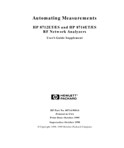
HP HP 8712ET User Manual Supplement (116 pages)
Automating Measurements, RF Network Analyzers
Brand:
HP
| Category:
Measuring Instruments
| Size: 0.55 MB
Table of Contents
Table of Contents
7
1 Introduction
11
2 Configuring Your Test System
15
Measurement System Configurations and Considerations
16
Stand-Alone Network Analyzers
17
External Computer Control
19
Expandability and Large Systems
21
Throughput Considerations
22
Selecting a Measurement Controller
23
Stand-Alone Operation Using IBASIC
23
Computer-Controlled HP-IB Operation
23
Computer-Controlled LAN Operation
24
Using IBASIC and External Control Together
24
Selecting a Programming Language
25
Hp Basic
25
Ibasic
25
Hp Vee
26
Microsoft® Quickbasic
26
C and C
26
VXI Plug&Play Driver
27
Example Programs
27
3 Operator Interaction
29
Prompting the Operator
32
Using Graphics to Create On-Screen Diagrams
33
User-Defined BEGIN Key Menu
34
Loading a User BEGIN Program
38
Modifying a User BEGIN Program
38
Using a Switch with User BEGIN
39
Using a Barcode Reader for Data Entry
41
Using an External Keyboard for Data Entry
42
Using the Analyzer's Title Feature
43
Hot Keys on External Keyboard for Common Functions
44
User-Defined TTL Input/Output
46
Using a Foot or Hand Switch
47
Limit-Test Pass/Fail TTL Input/Output
49
Analyzer Port Numbers
50
Output for External VGA-Compatible Monitor
52
4 Measurement Setup and Control with Fast Recall
53
Using Fast Recall with the Front Panel or a Keyboard
55
Using Fast Recall with a Switch
57
5 Automated Measurement Setup and Control
59
Setting the Instrument State
62
Recalling Instrument States from Disk
62
Using Learn Strings to Save and Recall Instrument States
64
SCPI Commands that Modify a Single Parameter
65
Fast Iterative Control
66
Responsive Communication Using Srqs
68
Using both of the Analyzer's Measurement Channels
69
Using Single Sweep to Measure and View All Four S-Parameters
70
AUTOST Files
73
6 Controlling Peripherals
75
Using the Parallel Port
77
Writing to the Parallel Port
80
Reading from the Parallel Port
83
Hardcopy Considerations
84
Using the Serial Port
85
7 Displaying Measurement Results
87
Graticule On/Off
89
Limit Testing
90
To Turn Limit Lines on or off
90
To Turn the Fail Icon on or off
90
To Turn the Pass/Fail Text on or off
90
To Move the Position of the Pass/Fail Indicator
91
Customized X-Axis Annotation
92
To Turn on User-Defined X-Axis Annotation
92
To Specify Your Start and Stop Values
92
To Specify a Custom SuffiX
92
To Turn the X-Axis Annotation on or off
93
Customized Measurement-Channel Annotation
94
To Turn on User-Defined Measurement-Channel Annotation
94
To Specify the String to be Displayed
94
To Restore Default Measurement-Channel Annotation
94
To Turn Measurement-Channel Annotation on or off
95
Markers
96
Title and Clock
98
8 Saving Measurement Results
99
Querying Measurement Data
101
Saving the Measurement to Disk - Save ASCII
102
Saving the Measurement to Disk - Save Data
103
Querying Marker Searches
104
Saving Measurement Results to Disk
105
Using Hardcopy Features to Print or Plot Results
106
Faster Hardcopies Using a PCL5 Printer
107
Customizing Page Layout
107
Custom Data Sheets
110
Statistical Process Control
112
Transferring Files
113
HP HP 8712ET Installation Note (7 pages)
Installation Instructions for the CPU Board HP 08714-60175 new and HP 08714-69175 rebuilt-exchange
Brand:
HP
| Category:
Measuring Instruments
| Size: 0.06 MB
Table of Contents
Parts List
3
Installation Procedure
4
System Options
4
Hewlett-Packard Sales and Service Offices
7
Advertisement
HP HP 8712ET Quick Start Manual (4 pages)
Brand:
HP
| Category:
Measuring Instruments
| Size: 0.18 MB
HP HP 8712ET Quick Start Manual (4 pages)
Cellular Antenna
Brand:
HP
| Category:
Antenna
| Size: 0.09 MB
HP HP 8712ET Quick Start Manual (4 pages)
CATV
Brand:
HP
| Category:
Measuring Instruments
| Size: 0.14 MB
Advertisement
Related Products
HP 8712B
HP HP 8712ES
HP 8712C
HP 8719ET
HP 8719ES
HP 8711C
HP 8713C
HP 8711B
HP 87114B
HP HP 8714ET
HP Categories
Desktop
Laptop
Server
Monitor
Switch
More HP Manuals
Login
Sign In
OR
Sign in with Facebook
Sign in with Google
Upload manual
Upload from disk
Upload from URL