Sign In
Upload
Manuals
Brands
Mitsubishi Electric Manuals
Inverter
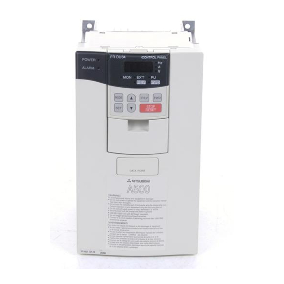
FR-A520-0.4K -55K
Mitsubishi Electric FR-A520-0.4K -55K Manuals
Manuals and User Guides for Mitsubishi Electric FR-A520-0.4K -55K. We have
1
Mitsubishi Electric FR-A520-0.4K -55K manual available for free PDF download: Instruction Manual
Mitsubishi Electric
FR-A520-0.4K -55K
Instruction Manual
Mitsubishi Electric FR-A520-0.4K -55K Instruction Manual (228 pages)
TRANSISTORIZED INVERTER, HIGH FUNCTION & LOW ACOUSTIC NOISE
Brand:
Mitsubishi Electric
| Category:
Inverter
| Size: 2.91 MB
Table of Contents
Safety Instructions
4
Fire Prevention
4
Table of Contents
7
Pre-Operation Information
11
Precautions for Operation
11
Basic Configuration
12
Structure
13
Appearance and Structure
13
Removal and Reinstallation of the
14
Removal and Reinstallation of the Operation Panel
16
Installation and Wiring
17
Installation
18
Instructions for Installation
18
Wiring
20
Terminal Connection Diagram
20
Wiring of the Main Circuit
23
Wiring of the Control Circuit
29
Connection to the PU Connector
33
Connection of Stand-Alone Option Units
35
Design Information
39
Other Wiring
40
Power Harmonics
40
Japanese Harmonic Suppression Guidelines
41
Inverter-Generated Noises and Reduction Techniques
44
Leakage Currents and Countermeasures
48
Inverter-Driven 400V Class Motor
49
Peripheral Devices
50
Instructions for Compliance with the UL and CSA Standards
52
Instructions for Compliance with the European Standards
53
Earthing (EC Version)
54
Pre-Operation Information
57
Devices and Parts to be Prepared for Operation
57
Power on
59
Installation Check
59
Parameter Check
59
Operation
65
Pre-Operation Checks
65
External Operation Mode (Operation Using External Input Signals)
66
PU Operation Mode (Operation Using the Operation Panel (FR-DU04))
67
Combined Operation Mode (Operation Using the External Input Signals and PU)
68
Parameter List
70
Parameter Function Details
76
Torque Boost (Pr. 0, Pr. 46, Pr. 112)
76
Output Frequency Range (Pr. 1, Pr. 2, Pr. 18)
77
Base Frequency, Base Frequency Voltage (Pr. 3, Pr. 19, Pr. 47, Pr. 113)
78
Multi-Speed Operation (Pr. 4 to Pr. 6, Pr. 24 to Pr. 27, Pr. 232 to Pr. 239)
79
Acceleration/Deceleration Time (Pr. 7, Pr. 8, Pr. 20, Pr. 21, Pr. 44, Pr. 45, Pr. 110, Pr. 111)
80
Electronic Overcurrent Protection (Pr. 9)
81
DC Dynamic Brake (Pr. 10, Pr. 11, Pr. 12)
82
Starting Frequency (Pr. 13)
83
Load Pattern Selection (Pr. 14)
83
Jog Operation (Pr. 15, Pr. 16)
84
MRS Input Selection (Pr. 17)
85
Stall Prevention (Pr. 22, Pr. 23, Pr. 66, Pr. 148, Pr. 149, Pr. 154)
86
Multi-Speed Input Compensation (Pr. 28)
87
Acceleration/Deceleration Pattern (Pr. 29, Pr. 140 to Pr. 143)
88
Regenerative Brake Duty (Pr. 30, Pr. 70)
89
Frequency Jump (Pr. 31 to Pr. 36)
90
Speed Display (Pr. 37, Pr. 144)
91
Up-To-Frequency Sensitivity (Pr. 41)
92
Output Frequency Detection (Pr. 42, Pr. 43, Pr. 50, Pr. 116)
92
Second/Third Stall Prevention (Pr. 48, Pr. 49, Pr. 114, Pr. 115)
93
Monitor Display/Fm, am Terminal Function Selection (Pr. 52 to Pr. 54, Pr. 158)
95
Monitoring Reference (Pr. 55, Pr. 56)
97
Automatic Restart after Instantaneous Power Failure (Pr. 57, Pr. 58, Pr. 162 to Pr. 165)
98
Remote Setting Function Selection (Pr. 59)
100
Intelligent Mode Selection (Pr. 60)
101
Acceleration/Deceleration Reference Current/Lift Mode Starting Frequency (Pr. 61 to Pr. 64)
103
Retry Function (Pr. 65, Pr. 67 to Pr. 69)
104
Applied Motor (Pr. 71)
106
PWM Carrier Frequency (Pr. 72, Pr. 240)
107
Voltage Input (Pr. 73)
108
Input Filter Time Constant (Pr. 74)
109
Reset Selection/Pu Disconnection Detection/Pu Stop Selection (Pr. 75)
109
Alarm Code Output Selection (Pr. 76)
111
Parameter Write Inhibit Selection (Pr. 77)
112
Reverse Rotation Prevention Selection (Pr. 78)
113
Operation Mode Selection (Pr. 79)
114
Motor Capacity/Number of Motor Poles/Speed Control Gain (Pr. 80, Pr. 81, Pr. 89)
117
Offline Auto Tuning Function (Pr. 82 to Pr. 84, Pr. 90 to Pr. 94, Pr. 96)
118
Online Auto Tuning Selection (Pr. 95)
124
V/F Control Frequency (Voltage) (Pr. 100 to Pr. 109)
126
Computer Link Operation (Pr. 117 to Pr. 124)
127
Setting Items and Set Data
133
Error Code List
135
PID Control (Pr. 128 to Pr. 134)
137
Commercial Power Supply-Inverter Switch-Over Function (Pr. 135 to Pr. 139)
144
Output Current Detection Function (Pr. 150, Pr. 151)
148
Zero Current Detection (Pr. 152, Pr. 153)
149
RT Signal Activated Condition Selection (Pr. 155)
150
Stall Prevention Function and Current Limit Function (Pr. 156)
150
OL Signal Output Timer (Pr. 157)
152
User Group Selection (Pr. 160, Pr. 173 to Pr. 176)
153
Watt-Hour Meter Clear/Actual Operation Hour Meter Clear (Pr. 170, Pr. 171)
154
Input Terminal Function Selection (Pr. 180 to Pr. 186)
154
Output Terminal Function Selection (Pr. 190 to Pr. 195)
157
User Initial Value Setting (Pr. 199)
159
Programmed Operation Function (Pr. 200 to Pr. 231)
160
Cooling Fan Operation Selection (Pr. 244)
164
Stop Selection (Pr. 250)
165
Power Failure-Time Deceleration-To-Stop Function (Pr. 261 to Pr. 266)
167
Stop-On-Contact, Load Torque High-Speed Frequency Selection (Pr. 270)
169
High-Speed Frequency Control (Pr. 271 to Pr. 274)
170
Operation Example
171
Z Stop on Contact (Pr. 275, Pr. 276)
174
Stop on Contact (Pr. 275, Pr. 276)
175
Brake Sequence Function (Pr. 278 to Pr. 285)
177
Droop Control (Pr. 286, Pr. 287)
181
Meter (Frequency Meter) Calibration (Pr. 900, Pr. 901)
182
Frequency Setting Voltage (Current) Bias and Gain (Pr. 902 to Pr. 905)
184
Buzzer Control (Pr. 990)
186
Errors (Alarms)
188
Error (Alarm) Definitions
188
Correspondences between Digital and Actual Characters
191
Alarm Code Output
192
Resetting the Inverter
192
Troubleshooting
193
Checking the Operation Panel Display at Alarm Stop
193
Faults and Check Points
194
Precautions for Maintenance and Inspection
196
Check Items
196
Periodic Inspection
196
Insulation Resistance Test Using Megger
197
Pressure Test
197
Checking the Inverter and Converter Modules
199
Replacement of Parts
200
Inverter Replacement
201
Measurement of Main Circuit Voltages, Currents and Power
202
Standard Specifications
205
Model Specifications
205
Common Specifications
207
Outline Drawings
209
Outline Drawing
212
Option List
214
Stand-Alone Options
214
Inboard Dedicated Options
216
Appendix 1 Data Code List
217
Appendix 1 Data Code List
218
Appendix 2 List of Parameters Classified by Purposes of Use
224
Appendix 3 Operating the Inverter Using a Single-Phase Power Supply
225
Advertisement
Advertisement
Related Products
Mitsubishi Electric FR-A520-0.4K-55K-NA
Mitsubishi Electric FR-A520-0.4K
Mitsubishi Electric FR-A520-0.75K
Mitsubishi Electric FR-A520-0.4K-NA
Mitsubishi Electric FR-A520-1.5K
Mitsubishi Electric FR-A520-30K
Mitsubishi Electric FR-A520-2.2K-NA
Mitsubishi Electric FR-A520-15K-NA
Mitsubishi Electric FR-A520-30K-NA
Mitsubishi Electric FR-A520-7.5K-NA
Mitsubishi Electric Categories
Air Conditioner
Controller
Projector
Inverter
Heat Pump
More Mitsubishi Electric Manuals
Login
Sign In
OR
Sign in with Facebook
Sign in with Google
Upload manual
Upload from disk
Upload from URL