Sign In
Upload
Manuals
Brands
Mitsubishi Electric Manuals
Controller
MELSEC-L Series
Mitsubishi Electric MELSEC-L Series Manuals
Manuals and User Guides for Mitsubishi Electric MELSEC-L Series. We have
10
Mitsubishi Electric MELSEC-L Series manuals available for free PDF download: User Manual, Basic User Manual, Programming Manual
Mitsubishi Electric MELSEC-L Series User Manual (1040 pages)
Brand:
Mitsubishi Electric
| Category:
Control Unit
| Size: 7.52 MB
Table of Contents
Safety Precautions
3
Introduction
14
Revisions
15
Table of Contents
16
Compliance with the Emc and Low Voltage Directives
24
Relevant Manuals
24
Terms
27
Packing List
28
Section 1 Product Specifications and Handling
29
Features of LD77MS
32
Positioning Control
32
Purpose and Applications of Positioning Control
36
Mechanism of Positioning Control
38
Overview of Positioning Control Functions
39
Outline Design of Positioning System
49
Communicating Signals between LD77MS and each Module
50
Flow of All Processes
54
Flow of System Operation
54
Outline of Starting
56
Outline of Stopping
58
Outline for Restarting
60
General Image of System
62
Component List
63
Applicable System
67
How to Check the Function Version and SERIAL no
68
Restrictions by the SERIAL No. and Version
69
Performance Specifications
72
LD77MS Control Functions
74
List of Functions
74
LD77MS Main Functions
77
LD77MS Sub Functions
79
LD77MS Common Functions
81
Combination of LD77MS Main Functions and Sub Functions
84
List of Input/Output Signals with PLC CPU
86
Specifications of Input/Output Signals with PLC CPU
86
Plc Cpu)
89
Details of Output Signals (PLC CPU LD77MS)
91
Electrical Specifications of Input Signals
93
Specifications of Interfaces with External Devices
93
Signal Layout for External Input Connection Connector
95
List of Input Signal Details
97
Interface Internal Circuit
99
External Circuit Design
104
Installation, Wiring and Maintenance Procedures
120
Outline of Installation, Wiring and Maintenance
120
Names of each Part
121
Handling Precautions
123
Installation
125
Precautions for Installation
125
Precautions for Wiring
126
Wiring
126
Precautions for Wiring
129
Confirming the Installation and Wiring
138
Items to Confirm When Installation and Wiring Are Completed
138
Disposal Instructions
139
Maintenance
139
Precautions for Maintenance
139
Parameters and Data Required for Control
142
Types of Data
142
Setting Items for Positioning Parameters
146
Setting Items for OPR Parameters
148
Setting Items for Expansion Parameters
149
Setting Items for Servo Parameters
149
Setting Items for Positioning Data
150
Setting Items for Block Start Data
152
Setting Items for Condition Data
153
Types and Roles of Monitor Data
154
Types and Roles of Control Data
159
Basic Parameters 1
163
List of Parameters
163
Basic Parameters 2
168
Detailed Parameters 1
169
Detailed Parameters 2
180
OPR Basic Parameters
192
OPR Detailed Parameters
200
Expansion Parameters
205
Servo Parameters
210
List of Positioning Data
223
List of Block Start Data
239
List of Condition Data
244
List of Monitor Data
254
System Monitor Data
254
Axis Monitor Data
268
List of Control Data
298
System Control Data
298
Axis Control Data
306
Precautions for Creating Program
344
List of Devices Used
348
Creating a Program
358
General Configuration of Program
358
Positioning Control Operation Program
359
Positioning Program Examples
363
Initialization Program
395
Program Details
395
Start Details Setting Program
396
Start Program
398
Continuous Operation Interrupt Program
410
Restart Program
412
Stop Program
415
Configuration and Roles of LD77MS Memory
420
Buffer Memory Area Configuration
423
Data Transmission Process
425
Machine OPR
442
Outline of OPR Control
442
Two Types of OPR Control
442
Machine OPR
446
Outline of the Machine OPR Operation
446
Machine OPR Method
447
OPR Method (1): Near-Point Dog Method
448
OPR Method (2): Count Method 1)
450
OPR Method (3): Count Method 2)
452
OPR Method (4): Data Set Method
454
OPR Method (5): Scale Origin Signal Detection Method
455
Fast OPR
458
Outline of the Fast OPR Operation
458
Outline of the OPR Setting Condition
460
Selection of the OPR Setting Condition
460
Outline of Major Positioning Controls
462
Data Required for Major Positioning Control
464
Operation Patterns of Major Positioning Controls
465
Designating the Positioning Address
475
Confirming the Current Value
476
Control Unit "Degree" Handling
478
Interpolation Control
481
Relation between each Control and Positioning Data
486
Setting the Positioning Data
486
1-Axis Linear Control
488
2-Axis Linear Interpolation Control
492
3-Axis Linear Interpolation Control
498
4-Axis Linear Interpolation Control
504
1-Axis Fixed-Feed Control
509
2-Axis Fixed-Feed Control (Interpolation)
512
3-Axis Fixed-Feed Control (Interpolation)
514
4-Axis Fixed-Feed Control (Interpolation)
519
2-Axis Circular Interpolation Control with Sub Point Designation
522
2-Axis Circular Interpolation Control with Center Point Designation
528
1-Axis Speed Control
536
2-Axis Speed Control
539
3-Axis Speed Control
543
4-Axis Speed Control
547
Speed-Position Switching Control (INC Mode)
552
Speed-Position Switching Control (ABS Mode)
563
Position-Speed Switching Control
572
Current Value Changing
582
NOP Instruction
587
JUMP Instruction
588
Loop
590
Lend
592
High-Level Positioning Control 10- 1 to
595
Outline of High-Level Positioning Control
596
Data Required for High-Level Positioning Control
597
Block Start Data" and "Condition Data" Configuration
598
High-Level Positioning Control Execution Procedure
600
Relation between Various Controls and Block Start Data
601
Setting the Block Start Data
601
Block Start (Normal Start)
602
Condition Start
604
Wait Start
605
Simultaneous Start
606
Repeated Start (for Loop)
607
Repeated Start (for Condition)
608
Restrictions When Using the NEXT Start
609
Relation between Various Controls and the Condition Data
610
Setting the Condition Data
610
Condition Data Setting Examples
613
Multiple Axes Simultaneous Start Control
615
Start Program for High-Level Positioning Control
620
Starting High-Level Positioning Control
620
Example of a Start Program for High-Level Positioning Control
621
Outline of Manual Control
626
Three Manual Control Methods
626
JOG Operation
628
Outline of JOG Operation
628
JOG Operation Execution Procedure
631
Setting the Required Parameters for JOG Operation
632
Creating Start Programs for JOG Operation
634
JOG Operation Example
636
Inching Operation
639
Outline of Inching Operation
639
Inching Operation Execution Procedure
642
Setting the Required Parameters for Inching Operation
643
Creating a Program to Enable/Disable the Inching Operation
644
Inching Operation Example
646
Manual Pulse Generator Operation
648
Outline of Manual Pulse Generator Operation
648
Manual Pulse Generator Operation Execution Procedure
652
Setting the Required Parameters for Manual Pulse Generator Operation
653
Creating a Program to Enable/Disable the Manual Pulse Generator Operation
654
Outline of Speed-Torque Control
658
Speed-Torque Control
658
Setting the Required Parameters for Speed-Torque Control
660
Setting the Required Data for Speed-Torque Control
661
Operation of Speed-Torque Control
663
Synchronous Control
689
Control Sub Functions 13- 1 to
691
Outline of Sub Functions
692
OPR Retry Function
694
Sub Functions Specifically for Machine OPR
694
OP Shift Function
698
Backlash Compensation Function
701
Functions for Compensating the Control
701
Electronic Gear Function
703
Near Pass Function
710
Functions to Limit the Control
712
Speed Limit Function
712
Torque Limit Function
714
Software Stroke Limit Function
718
Hardware Stroke Limit Function
724
Forced Stop Function
728
Advertisement
Mitsubishi Electric MELSEC-L Series Basic User Manual (382 pages)
MELSEC-L Ethernet Interface Module
Brand:
Mitsubishi Electric
| Category:
Controller
| Size: 7.71 MB
Table of Contents
Safety Precautions
3
Conditions of Use for the Product
7
Compliance with Emc and Low Voltage Directives
8
Introduction
8
Relevant Manuals
9
Table of Contents
10
Manual Page Organization
15
Terms
18
Packing List
20
Chapter 1 Features
21
Chapter 2 Part Names
27
Chapter 3 Specifications
29
General Specifications
29
Performance Specifications
29
Function List
31
Use with Other Functions
33
List of I/O Signals
34
Buffer Memory
36
Configuration of the Buffer Memory
36
List of Buffer Memory Addresses
37
Chapter 4 Procedures before Operation
57
Chapter 5 System Configuration
59
Overall System Configuration
59
Network Components
60
Applicable Systems
62
Chapter 6 Installation and Wiring
63
Installation
63
Wiring
64
Chapter 7 Communication Procedure
66
Setting Parameters Required for Communications
67
Parameter List
67
Basic Setting
68
Ethernet Operation Setting
69
Open Setting
71
TCP/IP Communications
74
Establishing a Connection
74
Communication Process
75
Active Open Procedure
77
Passive Open Procedure
79
UDP/IP Communications
81
Communication Process
81
Open Procedure
82
Chapter 8 Connecting Melsoft Products and a Got
84
Applications
84
Data Communication Procedure
85
Chapter 9 MC Protocol Communications
87
Applications
87
Communication Structure
88
Data Communication Procedure
89
Parameter Setting
90
Chapter 10 Slmp Communications
91
Applications
91
Communication Structure
92
Data Communication Procedure
93
Parameter Setting
94
Available Command List
95
Chapter 11 Data Communications Using the Predefined Protocol
97
Data Communication Procedure
99
Communication Type of Protocols
102
Packet Elements
103
Execution Condition of Predefined Protocol Communication
110
Example of Predefined Protocol Communications
113
System Configuration Example
113
Parameter Setting
114
Program Example
120
Chapter 12 Communications Using a Fixed Buffer
122
Applications
122
Differences between the "Procedure Exist" and "No Procedure" Control Methods
122
Communication Structure
123
Data Sending Procedure
125
Data Receiving Procedure
127
Data Receiving Using the Main Program (BUFRCV Instruction)
127
Data Receiving Using an Interrupt Program (BUFRCVS Instruction)
130
Parameter Setting
132
Parameter Setting When Using an Interrupt Program
133
Data Format
135
Header
135
Application Data
135
Pairing Open
141
Applications
141
Parameter Setting
142
Broadcast Communications
143
Sending/Receiving Procedures
143
Parameter Setting
145
Precautions
147
Example of Communications Using a Fixed Buffer
148
System Configuration
148
Parameter Setting
148
Program
152
Chapter 13 Communications Using a Random Access Buffer
156
Applications
156
Communication Structure
157
How Data Is Read from a Connected Device
158
How a Connected Device Writes Data
158
Parameter Setting
159
Data Format
160
Header
160
Application Data
161
Examples of Command and Response Formats
165
Precautions When Creating Programs
169
Physical and Logical Addresses of a Random Access Buffer
169
Example of Communications Using a Random Access Buffer
170
Chapter 14 Other Functions
171
Router Relay Function
171
Applications
171
Parameter Settings
171
Communications Using an Auto-Open UDP Port
176
Application
176
IP Filter Function
177
Application
177
Setting Method
178
Program Example
181
Precautions
182
Remote Password
183
Application
183
Remote Password Setting Processes (Unlock and Lock Processes)
184
Remote Password Check Procedure
185
Differences in Functions According to the Remote Password Check Status (Enabled/Disabled)
188
Precautions
190
Parameter Settings
192
Hub Connection Status Monitor Function
193
IP Address in Use Detection Function
194
Alive Check Function
196
Chapter 15 Dedicated Instructions
198
List of Dedicated Instructions
198
Parameter Settings for Using Dedicated Instructions
199
When Using Data Link Instructions
199
Precautions for Dedicated Instructions
200
Organization of the Dedicated Instruction Sections
200
Zp.open
201
Zp.close
205
Gp.ecprtcl
208
Zp.bufsnd
218
Zp.bufrcv
222
Z.bufrcvs
226
Zp.errclr
228
Zp.errrd
232
Zp.uini
235
Mitsubishi Electric MELSEC-L Series User Manual (238 pages)
Simple Motion Module
Brand:
Mitsubishi Electric
| Category:
Controller
| Size: 2.06 MB
Table of Contents
Safety Precautions
3
Conditions of Use for the Product
16
Introduction
17
Revisions
18
Table of Contents
19
Compliance with the Emc and Low Voltage Directives
22
Relevant Manuals
23
Manual Page Organization
26
Terms
28
Packing List
29
Outline of Synchronous Control
33
Chapter 1 Outline of Synchronous Control
34
Outline of Synchronous Control
34
Performance Specifications
38
Restrictions by the SERIAL No. and Version
41
Operation Method of Synchronous Control
43
Synchronous Control Execution Procedure
43
Starting/Ending for Synchronous Control
44
Stop Operation of Output Axis
46
Input Axis Module
49
Servo Input Axis
50
Chapter 2 Input Axis Module
50
Overview of Servo Input Axis
50
Servo Input Axis Parameters
52
Servo Input Axis Monitor Data
56
Synchronous Encoder Axis
58
Overview of Synchronous Encoder Axis
58
Setting Method for Synchronous Encoder
61
Synchronous Encoder Axis Parameters
69
Synchronous Encoder Axis Control Data
77
Synchronous Encoder Axis Monitor Data
81
Cam Function
85
Chapter 3 Cam Function
86
Control Details for Cam Function
86
Create Cam Data
94
Memory Configuration of Cam Data
94
Cam Data Operation Function
97
Cam Auto-Generation Function
101
Synchronous Control
105
Main Shaft Module
106
Chapter 4 Synchronous Control
106
Overview of Main Shaft Module
106
Main Shaft Parameters
107
Main Shaft Clutch Parameters
109
Main Shaft Clutch Control Data
117
Auxiliary Shaft Module
118
Overview of Auxiliary Shaft Module
118
Auxiliary Shaft Parameters
119
Auxiliary Shaft Clutch Parameters
121
Auxiliary Shaft Clutch Control Data
129
Clutch
130
Overview of Clutch
130
Control Method for Clutch
130
Smoothing Method for Clutch
137
Use Example of Clutch
142
Speed Change Gear Module
143
Overview of Speed Change Gear Module
143
Speed Change Gear Parameters
144
Output Axis Module
146
Overview of Output Axis Module
146
Output Axis Parameters
148
Synchronous Control Change Function
152
Overview of Synchronous Control Change Function
152
Synchronous Control Change Control Data
153
Synchronous Control Monitor Data
158
Phase Compensation Function
163
Output Axis Sub Functions
166
Advertisement
Mitsubishi Electric MELSEC-L Series Programming Manual (196 pages)
MELSAP-L
Brand:
Mitsubishi Electric
| Category:
Controller
| Size: 9.23 MB
Table of Contents
Conditions of Use for the Product
3
Introduction
3
Safety Precautions
3
Table of Contents
4
Relevant Manuals
7
Terms
8
Chapter 1 General Description
9
Description of SFC Program
11
SFC (MELSAP-L) Features
12
Chapter 2 System Configuration
19
Applicable CPU Modules
19
Peripheral Devices for SFC Programs
20
Chapter 3 Specifications
21
Performance Specifications Related to SFC Programs
21
Device List
25
Processing Time
32
Processing Time for SFC Program
32
Processing Time for S(P).SFCSCOMR Instruction and S(P).SFCTCOMR Instruction
36
Calculating the SFC Program Capacity
38
Method for Calculating the SFC Program Capacity
38
Number of Steps Required for Expressing the SFC Diagram as SFC Dedicated Instructions
39
Chapter 4 Sfc Program Configuration
40
List of SFC Diagram Symbols
41
Steps
44
Step (Without Step Attribute)
44
Initial Step
47
Dummy Step
48
Coil HOLD Step
48
Operation HOLD Step (Without Transition Check)
50
Operation HOLD Step (with Transition Check)
51
Reset Step
53
Block START Step (with END Check)
54
Block START Step (Without END Check)
55
End Step
57
Instructions that Cannot be Used with Operation Outputs
59
Transition
60
Serial Transition
60
Selection Transition
62
Parallel Transition
65
Jump Transition
69
Precautions for Creating Operation Output (Step)/Transition Condition Programs
70
Controlling SFC Programs by Instructions (SFC Control Instructions)
74
Step Operation Status Check Instructions (A, B, &A, &B, |A, |B) [Sn/Blm\Sn]
78
Forced Transition Check Instruction (A, B, &A, &B, |A, |B) [Trn/Blm\Trn]
81
Block Operation Status Check Instruction (A, B, &A, &B, |A, |B) [Blm]
84
Active Step Batch Readout (MOV and DMOV)
86
Active Step Batch Readout (BMOV)
89
Block START & END Instructions (S, R) [Blm]
92
Block STOP and RESTART Instructions (PAUSE, RSTART) [Blm]
94
Step START and END Instructions (S, R) [Sn/Blm\Sn]
97
Forced Transition EXECUTE & CANCEL Instructions (S, R) [Trn/Blm\Trn]
101
Active Step Change Instruction (SCHG)
103
Block Switching Instruction (BRSET)
105
SFC Information Devices
107
Block START/END Bit
108
Step Transition Bit
110
Block STOP/RESTART Bit
112
Block STOP Mode Bit
114
Continuous Transition Bit
116
Number of Active Steps Register
118
Step Transition Watchdog Timer
119
SFC Operation Mode Setting
121
SFC Program Start Mode
122
Block 0 START Condition
124
Output Mode at Block STOP
125
Periodic Execution Block Setting
127
Operation Mode at Double Block START
128
Operation Mode at Transition to Active Step (Double Step START)
129
SFC Comment Readout Instruction
132
SFC Comment Readout Instruction (S(P). SFCSCOMR)
133
SFC Transition Comment Readout Instruction (S(P). SFCTCOMR)
140
Chapter 5 Sfc Program Processing Sequence
147
Whole Program Processing of Basic Model QCPU
147
Whole Program Processing Sequence
147
Whole Program Processing of High Performance Model QCPU, Process CPU, Redundant CPU, Universal Model QCPU, and LCPU
148
Whole Program Processing Sequence
148
Execution Type Designation by Instructions
150
SFC Program for Program Execution Management
152
SFC Program Processing Sequence
154
SFC Program Execution
154
Block Execution Sequence
156
Step Execution Sequence
157
Continuous Transition ON/OFF Operation
158
Chapter 6 Sfc Program Execution
160
SFC Program START and STOP
160
SFC Program Resumptive START Procedure
161
Mitsubishi Electric MELSEC-L Series User Manual (168 pages)
Brand:
Mitsubishi Electric
| Category:
Controller
| Size: 6.68 MB
Table of Contents
Safety Precautions
3
Conditions of Use for the Product
9
Introduction
10
Relevant Manuals
11
Table of Contents
12
Manual Page Organizattion
16
Terms
19
Chapter 1 Data Logging
20
Features
20
Processing Outline
23
Chapter 2 System Configuration
24
Overall System Configuration
24
Software
25
Connection from a USB or Serial Port
26
Connection from an Interface Board
29
Connection Precautions
30
Operating Environment for the Configuration Tool
31
Chapter 3 Specifications
32
Function Specifications
32
Folder Structure
34
CSV File Output Format
35
CSV Format Specifications
35
Output Details of Lines and Columns
35
Value Ranges by Output Format
40
Chapter 4 Preparation and Setup
41
Chapter 5 Start-Up of the Configuration Tool
43
Getting the Configuration Tool
43
Installation Method
44
Installation Procedure
44
Uninstallation Procedure
49
Starting the Configuration Tool
50
Chapter 6 Data Logging Function
51
Target Data
52
Sampling of Target Data
53
Logging Type
58
Continuous Logging
58
Trigger Logging
59
Trigger Condition
61
Data Logging Status
64
Data Logging File
66
Saving Format of the Data Logging File
66
How Sampled Data Are Saved
66
File Switching Setting
67
Buffer Capacity
70
Data Missing
71
Precautions for the Data Logging Function
73
Chapter 7 Other Functions
76
Data Logging Operation at Transition to RUN
76
Auto Logging by Inserting an SD Memory Card
77
File Access
80
Chapter 8 How to Use the Configuration Tool
81
Setting Flow Chart
81
Screen Structure
82
Main Screen
82
Menu Structure
83
Toolbar Structure
84
Edit Item Tree
85
Status Bar
86
Common Operations
87
Device Batch Replacement
88
Project Management
89
Creating a New Project
89
Opening a Project
89
Saving a Project
91
Reading the Logging Setting from the SD Memory Card
92
Writing the Logging Setting into the SD Memory Card
94
Data Logging Setting
96
Data Logging Setting List
96
Change of the Data Logging Setting Screen
98
Logging Type
100
Sampling
101
Data
103
Batch Data Insertion
105
Trigger
106
Number of Logging Lines
108
CSV Output
109
Save
111
Movement
113
Finish
114
Common Setting
115
Auto Logging Setting
116
Buffer Capacity Setting
117
Transfer Setup
118
Connection with a USB or Ethernet Cable
118
Connection Via a Network
120
Connection Test
122
Connection Channel List
123
Searching CPU Modules on the Network
124
Read Logging Setting
126
Write Logging Setting
128
Delete Logging Setting
130
Logging Status and Operation
132
Logging File Operation
135
Checking the Product Information
137
Checking the Version Information
137
Opening the User's Manual
137
Available Characters
138
Available ASCII Characters
138
Characters Available for File and Folder (Directory) Names
139
Mitsubishi Electric MELSEC-L Series User Manual (134 pages)
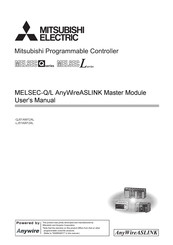
MELSEC-Q/L AnyWireASLINK Master Module
Brand:
Mitsubishi Electric
| Category:
Controller
| Size: 4.15 MB
Table of Contents
Copyright
3
Precautions Regarding Warranty and Specifications
3
Safety Precautions
4
Conditions of Use for the Product
13
Compliance with Emc and Low Voltage Directives
14
Introduction
14
Relevant Manuals
15
Table of Contents
16
Manual Page Organization
19
Terms
20
Packing List
21
Chapter 1 Features
22
Anywireaslink
22
Features
23
Chapter 2 Part Names
25
Chapter 3 Specifications
27
General Specifications
27
Performance Specifications
28
Performance List
28
Number of Parameters to Set
30
Communication Performance
31
Function List
34
List of I/O Signals
35
List of Buffer Memory Addresses
36
Chapter 4 Procedures before Operation
37
Chapter 5 System Configuration
39
Overall Configuration
39
System Configuration of the Master Module
39
System Configuration of Anywireaslink
41
Applicable Systems
42
Qj51Aw12Al
42
Lj51Aw12Al
43
Compatible Software Version
44
Chapter 6 Installation and Wiring
45
Installation Environment and Position of the Master Module
45
Wiring
45
Wiring Precautions
47
Connection of Slave Modules
48
Power Supply to the Anywireaslink System
49
Check before Power-On
53
Power-On
53
Terminating Unit
54
Chapter 7 Various Settings
55
Master Module Operation Mode Setting
55
Master Module Addition
55
Switch Setting
56
Auto Refresh
56
Slave Module Address Setting
57
Automatic Address Detection Function
59
Performing the Automatic Address Detection
59
Interlock Program
61
Automatic Address Detection Execution Timing
62
Automatic Reading of the System Configuration
63
Chapter 8 Functions
64
Bit Transmission Function
64
Transmission Cable Short Detection Function
64
Disconnected Transmission Cable Location Detection Function
65
Transmission Cable Voltage Drop Detection Function
66
Parameter Access Error Detection Function
67
Same ID Used Detection Function
69
Module with no ID Setting Detection Function
70
Reading and Writing Parameters
71
Backup/Restoring Function
76
Chapter 9 Programming
77
Correlations between Devices
77
System Using the QJ51AW12AL
78
When Using a Module in the Ordinary System Configuration
78
When Connecting a Module in a Remote I/O Station
80
System Using the LJ51AW12AL
87
When Using a Module in the Ordinary System Configuration
87
When Connecting a Module to a Head Module
89
Mitsubishi Electric MELSEC-L Series Programming Manual (110 pages)
QnA Programming Manual (PID Control Instructions)
Brand:
Mitsubishi Electric
| Category:
Controller
| Size: 7.9 MB
Table of Contents
Safety Precautions
3
Conditions of Use for the Product
5
Table of Contents
6
Manuals
8
Relevant Manuals
8
Generic Terms
11
Chapter 1 General Description
12
PID Processing Method
13
Chapter 2 System Configuration for Pid Control
14
Applicable CPU
15
Chapter 3 Pid Control Specifications
16
PID Control by Incomplete Derivative
16
Performance Specifications
16
PID Operation Block Diagram and Operation Expressions
17
PID Control Instruction List
18
PID Control by Complete Derivative
22
Performance Specifications
22
PID Operation Block Diagram and Operation Expressions
22
PID Control Instruction List
23
Chapter 4 Functions of Pid Control
27
Outline of PID Control
27
Functions of PID Control
28
Operation Method
28
Forward Operation and Reverse Operation
28
Proportional Operation (P Operation)
29
Integral Operation (I Operation)
30
Derivative Operation (D Operation)
31
PID Operation
32
Other Functions
33
Bumpless Changeover Function
33
MV Upper/Lower Limit Control Function
33
Function for Transfer to the SV Storage Device for the PV in Manual Mode
34
Changing the PID Control Data or Input/Output Data Setting Range (for QCPU and LCPU)
35
Chapter 5 Pid Control Procedure
36
PID Control Data
38
Number of Loops to be Used and the Number of Loops to be Executed in a Single Scan
51
Sampling Cycle
52
I/O Data
53
Chapter 6 Pid Control Instructions
58
Chapter 7 How to Read Explanations for Instructions
60
Chapter 8 Incomplete Derivative Pid Control Instructions and Program Examples
62
PID Control Instructions
62
PID Control Data Settings
62
PID Operation
63
Operation Stop/Start of Designated Loop no
65
Parameter Change at Designated Loop
66
8.2 PID Control Program Examples
68
System Configuration for Program Examples
68
Program Example for Automatic Mode PID Control
68
Program Example for Changing the PID Control Mode between Automatic and Manual
71
Chapter 9 Complete Derivative Pid Control Instructions and Program Examples
74
Mitsubishi Electric MELSEC-L Series User Manual (102 pages)
Programmable Controller
Brand:
Mitsubishi Electric
| Category:
I/O Systems
| Size: 5.55 MB
Table of Contents
Safety Precautions
3
Conditions of Use for the Product
8
Introduction
9
Compliance with Emc and Low Voltage Directives
10
Relevant Manuals
11
Table of Contents
12
Manual Page Organization
14
Discontinued Models
16
Packing List
16
Terms
16
Chapter 1 Product Lineup
17
Product Lineup
17
How to Read the Model Name
18
Chapter 2 Part Names
20
Chapter 3 Before Using I/O Module
22
Input Module
22
Output Module
23
I/O Combined Module
30
Chapter 4 Specifications
31
General Specifications
31
Input Module Specifications
32
LX10 AC Input Module
32
LX28 AC Input Module
34
LX40C6 DC Input Module
35
LX41C4 DC Input Module
37
LX42C4 DC Input Module
39
Output Module Specifications
41
LY10R2 Contact Output Module
42
LY18R2A Contact Output Module (All Points Independent)
43
LY20S6 Triac Output Module
44
LY28S1A Triac Output Module (All Points Independent)
45
LY40NT5P Transistor Output Module (Sink Type)
47
LY41NT1P Transistor Output Module (Sink Type)
48
LY42NT1P Transistor Output Module (Sink Type)
50
LY40PT5P Transistor Output Module (Source Type)
52
LY41PT1P Transistor Output Module (Source Type)
53
LY42PT1P Transistor Output Module (Source Type)
55
I/O Combined Module Specifications
56
LH42C4NT1P DC Input/Transistor Output Combined Module (Sink Type)
57
LH42C4PT1P DC Input/Transistor Output Combined Module (Source Type)
59
Chapter 5 System Configuration
61
Chapter 6 Installation and Wiring
64
Installation Environment and Installation Position
64
Wiring
65
For the 18-Point Screw Terminal Block Module
65
For the 40-Pin Connector Type Module
67
Input Wiring Examples
69
Chapter 7 Various Settings
71
Input Response Time Setting
71
Error Time Output Mode Setting
73
Mitsubishi Electric MELSEC-L Series User Manual (80 pages)
AnyWire DB A20 Master Module
Brand:
Mitsubishi Electric
| Category:
Controller
| Size: 1.89 MB
Table of Contents
Copyright
3
Precautions Regarding Warranty and Specifications
3
Safety Precautions
5
Conditions of Use for the Product
14
Compliance with Emc and Low Voltage Directives
15
Table of Contents
16
Terms
18
Chapter 1 Overview
19
Chapter 2 Specifications
21
General Specifications
21
Performance Specifications
22
Power Supply Sequence and Handling of I/O Data
23
Applicable System
24
Qj51Aw12D2
24
Lj51Aw12D2
24
External Dimensions
26
Part Names
27
Module Mounting
27
Checking Function Version and Serial Number
27
Chapter 3 Operation Mode
28
Qj51Aw12D2
28
Transmission Speed Setting
28
Setting of the Number of Transmission Points, Double Check Mode, and Waveform Output
30
Method
30
Lj51Aw12D2
36
Setting of the Number of Transmission Points
38
Transmission Speed Setting
39
Double Check Mode Setting
40
Waveform Output Method Setting
42
Chapter 4 Programming
43
I/O Signals with CPU Module
43
I/O Signal List
43
Details of the Input Signal
44
Details of the Output Signal
44
Buffer Memory Area
45
I/O Area
46
Number of Error Addresses
46
Value of Error Addresses
46
Number of Connection Addresses
47
Value of Connection Addresses
47
Latest Error Code Storage Area, Latest Error ID Storage Area
47
Program Example
48
Chapter 5 Monitoring Function
50
Automatic Address Detection
50
Executing the Automatic Address Detection Function
51
Monitoring Operation
51
Chapter 6 Led Display
52
Qj51Aw12D2
52
Lj51Aw12D2
53
Chapter 7 Connections
54
Description of Terminals
54
Transmission Cable Terminal Block
55
Cable Processing
56
Terminating Unit
57
Mitsubishi Electric MELSEC-L Series User Manual (66 pages)
Brand:
Mitsubishi Electric
| Category:
Control Unit
| Size: 2.16 MB
Table of Contents
Safety Precautions
3
Conditions of Use for the Product
5
Introduction
6
Table of Contents
8
Relevant Manuals
10
How to Use this Manual
11
Terms
12
Chapter 1 Overview
13
Programmable Controller Monitoring Via Internet Using Web Function
13
Access Function to Programmable Controller
14
Availability of Communication Library and Sample Screen
14
Utilizing Web Server
15
Remote Password Check Function
16
Chapter 2 System Configurations
17
System Configurations
17
Precautions for Using Web Function
19
Chapter 3 Operating Procedure
21
General Procedure up to Communication Using Web Function
21
How to Obtain and Set up Communication Library and Sample Screen
23
Chapter 4 Verifying Operation of Web Function Using Sample Screen
26
Web Function Items Available on Sample Screen
26
Operating Procedure
27
Explanation of Sample Screen
28
Example of Data Communication on Sample Screen
29
Device Read/Write
31
Remote RUN/STOP
35
Data Request
37
Proxy Setting
40
Configurations of Files on Sample Screen
42
Chapter 5 Example of Creating File for Accessing Programmable Controller
44
Configuration of User-Created Screen
44
File Configuration
46
File Content
46
Chapter 6 Communication Library Functions
54
List of Supported Communication Library Functions
54
Communication Library Functions
54
Arguments Used by Functions
56
Return Values of Functions
58
Index
60
Revisions
62
Warranty
63
Trademarks
64
Advertisement
Related Products
Mitsubishi Electric MELSEC L series
Mitsubishi Electric MELSEC-L SSCNETIII/H
Mitsubishi Electric MELSEC L-Series
Mitsubishi Electric MELSEC-L02SCPU-P
Mitsubishi Electric MELSEC-L26CPU-BT
Mitsubishi Electric MELSEC-L CC-Link
Mitsubishi Electric MELSEC-LD77MH4
Mitsubishi Electric MELSEC-L26CPU-PBT
Mitsubishi Electric MELSEC-L26CPU-P
Mitsubishi Electric MELSEC-L26CPU
Mitsubishi Electric Categories
Air Conditioner
Controller
Projector
Inverter
Heat Pump
More Mitsubishi Electric Manuals
Login
Sign In
OR
Sign in with Facebook
Sign in with Google
Upload manual
Upload from disk
Upload from URL