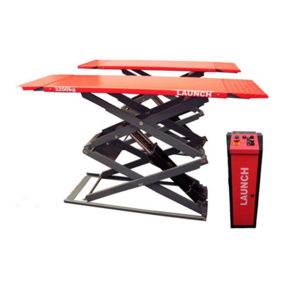
Table of Contents
Advertisement
LAUNCH
Contents
1 Precautions..............................................2
2 Structure and Working Principle..................3
2.1 Structure.................................................3
2.2 Electrical Diagram....................................4
2.3 Hydraulic Diagram.....................................5
2.4 Hydraulic Components in Control Desk.........5
2.5 Pneumatic Diagram..................................6
3 Tools .......................................................7
4 Unpacking................................................7
5 Installation................................................7
5.1 Basic Requirements..................................7
INSTALLATION MANUAL
5.2 Installation Procedures..............................7
5.2.1 Base Frame Installation..........................7
5.2.2 Control Desk Installation.........................8
5.2.3 Hydraulic Hose Connection......................9
5.2.4 Anchoring ............................................10
5.2.5 Air Hose Connection..............................12
6 Adjustment...............................................11
6.1 Preparations............................................11
6.2 Adjustment Procedures..............................11
8 Parts List...................................................13
Drawing of hydraulic system.............................13
1
TLT632AF INSTALLATION MANUAL
Advertisement
Table of Contents

Summary of Contents for Launch TLT632AF
-
Page 1: Table Of Contents
LAUNCH TLT632AF INSTALLATION MANUAL INSTALLATION MANUAL Contents 1 Precautions……………………………………….2 5.2 Installation Procedures……….…………...…..7 2 Structure and Working Principle……….…..3 5.2.1 Base Frame Installation……….…….….…..7 2.1 Structure…….…………………………………...3 5.2.2 Control Desk Installation….……….….…….8 2.2 Electrical Diagram……………………………...4 5.2.3 Hydraulic Hose Connection…………...…..9 2.3 Hydraulic Diagram…………..……………..5 5.2.4 Anchoring ………..…………..……...……..10 2.4 Hydraulic Components in Control Desk……...5... -
Page 2: Precautions
Check the components against parts list before designed purpose. installation. In case of any questions, please contact your dealer or Launch Tech. For the sake of technical improvements, Launch (Shanghai) Machinery Co., Ltd reserves the right to change the specifications without prior notice. -
Page 3: Structure And Working Principle
LAUNCH TLT632AF INSTALLATION MANUAL 2 Structure and Working 2.1 Structure Principle Fig.1... -
Page 4: Electrical Diagram
LAUNCH TLT632AF INSTALLATION MANUAL 2.2 Electrical Diagram AC220V/380V 3PH FU2/ ( 0.5A ) FU3 (3A ) Fig.2 Lifting process: Press UP button SB1, The motor will solenoid valve YV1, YV2 will be engaged, the safety system drive the pump and send oil to the cylinder, which will in turn is locked. -
Page 5: Hydraulic Diagram
LAUNCH TLT632AF INSTALLATION MANUAL 2.3 Hydraulic Diagram F2 F1 Fig.3 2.4 Hydraulic Components in Control Desk Fig.4... -
Page 6: Tools
LAUNCH TLT632AF INSTALLATION MANUAL Under normal working conditions, equalization valves (8) For emergency lowering, open 2 emergency lowering valves and emergency lowering valves (9) are closed. Oil flows to (9) to lower the lift slowly and carefully. The lowering speed the lower chamber of master cylinder through check valve can be adjusted by speed valve (11). -
Page 7: Unpacking
LAUNCH TLT632AF INSTALLATION MANUAL not exceed 5mm (0.2”). Slight slope can be 4 Unpacking corrected with shims. Excessive slope on the The lift is delivered in one package: 2 platforms ground will greatly affect the performance of the lift. ... -
Page 8: Control Desk Installation
LAUNCH TLT632AF INSTALLATION MANUAL Warnings: drawing two parallel lines (1# and 2#) on the concrete floor, the tolerance should less than 3mm The base is the edge of Floor plate. The tolerance should less than 6mm (0.24”) (0.1”). Draw four parallel lines (a, b, c, d), vertical with 1# Drawing the frame is very important. -
Page 9: Anchoring
LAUNCH TLT632AF INSTALLATION MANUAL Make sure the oil level is above the standard level. 5.4 Power supply connection Open the control desk, connect the wires according DO NOT operate the lift if oil tank is empty. Fix all the oil hoses and press UP button, test the to the electrical diagram. -
Page 10: Adjustment
LAUNCH TLT632AF INSTALLATION MANUAL The depth of the hole depends on the length of the Remove the dust from the holes. bolt. It is advisable that the bolts above the base Tap the bolt into the hole, insert and hit the core until ... -
Page 11: Parts List
This parts list is only to be used by maintenance and servicing personnel. The manufacturer is not responsible in case it is used for any other purposes. If any parts get damaged, please order from your dealer or Launch Tech. - Page 12 LAUNCH TLT632AF INSTALLATION MANUAL ERP CODE NAME 201021438 Base frame 103202084 Down inner scissor assembly 201021503 Scissor bracket 104991231 Slide block 103202086 Long axle 201021497 Scissor bracket 103202087 Connecting axle 103202088 Connecting axle I 103202091 Connecting long axle 201021436 Scissor bracket...
- Page 13 LAUNCH TLT632AF INSTALLATION MANUAL 201013188 Cylinder cover Y201013055D Scissor cover 103260111 Axle cover 2020 103260106 Axle cover 2525 103260195 Axle cover 2025 103260108 Axle cover 3025 103260194 Axle cover 2825 Hydraulic diagram ERP CODE NAME 103260191 C type 4M end high pressure oil hose 103260190 C type bending head 3.5M high pressure oil hose...
- Page 14 LAUNCH TLT632AF INSTALLATION MANUAL 103990191 Power unit assembly (220V/60Hz three phase) 103990192 Power unit assembly (220V/60Hz single phase) 103990193 Power unit assembly (200V/60Hz single phase)
- Page 15 LAUNCH TLT632AF INSTALLATION MANUAL Electrical diagram ERP CODE NAME 102130034 Transformer 102270004 Rectifier 103180018 Connecting board 102110059 Contactor 102150053 Fuse 102240039 Solenoid valve 102100137 Button 102100087 Power switch 102140018 Alarm 102990065 Indicating light 103160033 Solenoid air valve 102100135 Button 102100136 Button Equipment record (6 pages) attached.

