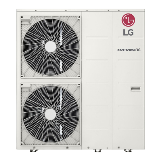
Summary of Contents for LG Therma V R32
- Page 1 Gen 3 R32 Mono General Installation Instructions. World Heat Cylinders - October 2019...
- Page 2 Therma V R32 Installation. Outdoor Installation. • Prepare a strong and level base. • Place on 3 anti vibration feet, & anchor to base. • Ensure the unit is 300mm from the wall. • The flow & return connections are 1” male.
- Page 3 Therma V R32 Installation. Outdoor Installation – Bill of Materials.
- Page 4 Therma V R32 Installation. Outdoor Installation with Domestic Hot Water Tank.
- Page 5 Therma V R32 Installation. Outdoor Installation with Domestic Hot Water Tank.
- Page 6 Therma V R32 Installation. Outdoor Installation – Frost Protection...
- Page 7 Therma V R32 Installation. Outdoor Installation – Power Cable. • RCD – Type C. • Rotary Enclosed Isolation switch – IP65. • Mandatory electricity meter fitted within an enclosed box. • Ensure power cable does not touch refrigerant pipework.
- Page 8 Therma V R32 Installation. Outdoor Installation – Terminal Blocks. Honeywell 2 wire, 3-Way Valve. • Terminal 8 – L – Port A - DHW Cylinder. • Terminal 10 – Neutral.
- Page 9 Therma V R32 Installation. Outdoor Installation – Terminal Block.
- Page 10 Therma V R32 Installation. Outdoor Installation – Terminal Block. 240V AC Realy Please see wiring diagram, Slides 15 & 16...
- Page 11 Therma V R32 Installation. Central Controller.
- Page 12 Therma V R32 Installation. DHW Installation • Remove lid/top of unit. • Feed the DHW water tank sensor into the back of the unit, shown in the diagram. • Connect the red connector to the main PCB( Top right hand side of unit) Terminal CN_TH4, the 7 terminal down, from the top right.
- Page 13 Therma V R32 Installation. DHW Installation – Tank Heater Wire from Terminal Pins 6&7 to Pins 5&6 on the DHW Tank Kit. Wire CN_B/HEAT(A) to Terminal Pins 6&7...
- Page 14 Therma V R32 Installation.
- Page 15 Therma V R32 Installation.
- Page 16 Therma V R32 Installation.
- Page 17 Therma V R32 Installation. Configuration - Dip Switches...
- Page 18 Therma V R32 Installation. Configuration - Dip Switches – SW2 Description Setting Default Role when central Controller 1 - Down – As Master Down is equipped. Accessory installation info 2 – Down Down Accessory installation info 3 – Up DHW Tank...
- Page 19 Therma V R32 Installation. Configuration – Installer Settings. Software Version Press the Right arrow to select:- Menu. Press Ok, Settings is shown. Press the up button for 3 seconds. Insert the Password – Shown in the bottom right corner (Software Version)
- Page 20 Therma V R32 Installation. Configuration – Installer Setting...
- Page 21 Therma V R32 Installation. Configuration – Installer Setting 3 Minutes Delay – Factory Use Only Select Temperature Sensor – Value Water Water & Air Dry Contact Mode Can only be used when dry contact device is separately purchased and installed...


