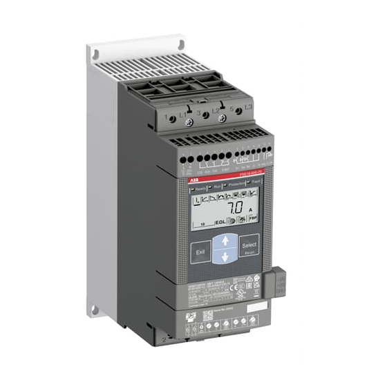
ABB PSE18 Replacing Manual
Changing of hmi module
Hide thumbs
Also See for PSE18:
- User manual (192 pages) ,
- Installation and commissioning manual (104 pages)
Advertisement
Table of Contents
Softstarter
1SFC132063M0201
PSE18...370
Contents
1. ESD Warning ................................................................................................................... 2
2. Tools ................................................................................................................................ 3
3. Step by step ..................................................................................................................... 4
4. Configuration of the HMI module ..................................................................................... 7
April-16
Changing of HMI Module
PSE18...370
Advertisement
Table of Contents

Summary of Contents for ABB PSE18
- Page 1 Softstarter Changing of HMI Module PSE18…370 1SFC132063M0201 April-16 PSE18…370 Contents 1. ESD Warning ........................2 2. Tools ..........................3 3. Step by step ........................4 4. Configuration of the HMI module ..................7...
- Page 2 Safety information Warning! A quali ed electrician must carry out installation, commissioning and service on the product by following installation standards and regulations. The product user hazardous voltage that can cause death or serious injury. Always disconnect power before working on equipment. Do not touch terminals when voltage is applied, output terminals can have live voltage even when the device is in o position.
-
Page 3: Esd Warning
1. ESD Warning Please note! The life span of electronics can be affected by damage caused by electrostatic discharge. This can happen if a charged tool or person touches a component. Therefore it is very important that all tools and personnel are discharged by touching an earthed point before the printed circuit board or any of the components are touched. -
Page 4: Step By Step
3. Disconnect all cables from the terminals 1 through 14, external keypad and the fieldbus plug accessory. 4. Disconnect the cables from 1L1, 3L2, 5L3, 2T1, 4T2, 6T3. For PSE18…105 remove the connection unit. 5. Detach the HMI module with a small screwdriver. - Page 5 15. Mount the cables on the sub-board according to the fig. below. It is very important that each cable is correctly mounted to the correct terminal. PSE18…105 Temp. sensor CT L1 Bypass L1 Bypass L3 CT L3 PSE142…170 From thyristor L1 From thyristor L3 Temp.
- Page 6 18. For PSE210…370 connect the cable between the main board and the sub board. 19. Mount the HMI module. 20. For PSE18…105 mount the connection unit. 21. Connect the cables to 1L1, 3L2, 5L3 (main voltage) and 2T1, 4T2, 6T3 (motor connection).
-
Page 7: Configuration Of The Hmi Module
4. Configuration of the HMI module The HMI module is programmed for PSE18, follow the step below to change to the correct size of the Softstarter: 1. Switch on the power supply (terminal 1 and 2). 2. Press and hold the “Exit”, “Select”, “arrow up” buttons for 3 sec.


