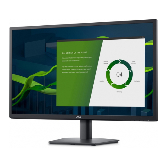
Dell E2722H Service Manual
27" led monitor
Hide thumbs
Also See for E2722H:
- User manual (28 pages) ,
- Service manual (22 pages) ,
- User manual (72 pages)
Table of Contents
Advertisement
Quick Links
Advertisement
Table of Contents

Summary of Contents for Dell E2722H
- Page 1 27" LED Monitor Dell E2722H Service Service Service Simplified...
-
Page 2: Important Safety Notice
Accordingly, a servicer who uses a service procedure or tool which is not recommended by DELL must first satisfy himself thoroughly that neither his safety nor the safe operation of the equipment will be jeopardized by the service method selected. - Page 3 1. Exploded view diagram with list of items 2. Wiring connectivity diagram...
-
Page 4: Tools Required
3. Tools Required List the type and size of the tools that would typically can be used to disassemble the product to a point where components and materials requiring selective treatment can be removed. Tool Description: ‐ Screwdriver (Phillip-head, Hexagonal head) ‐... - Page 5 Unscrew the 4 screws by the Philips-head Screwdriver and insert the scraper into the button site to open the rear cover Remove all the aluminum foil and the cable connectors and Remove the Unscrew the two mainframe screws on the two sites of mainframe remove the mylar on the powerboard...
- Page 6 Unscrew the screws on the boards Remove the mainboard and power board Unscrew the two Hexagonal screws Mainboard powerboard panel...
-
Page 7: Assembly Procedures
3.2 Assembly Procedures: screw the screws on Assemble the mainboard and the boards powerboard Assemble the maylar stick all the aluminum foil and connect the cable Assemble and screw the two screws on the two mainframe sites of mainframe... -
Page 8: Troubleshooting Instructions
Assemble screw the six screws the rear by the Philips-head cover Screwdriver Push the stand in Assemble and tighten the the stand screw on the stand ass’y ass’y 4. Trouble shooting instructions...


