Table of Contents

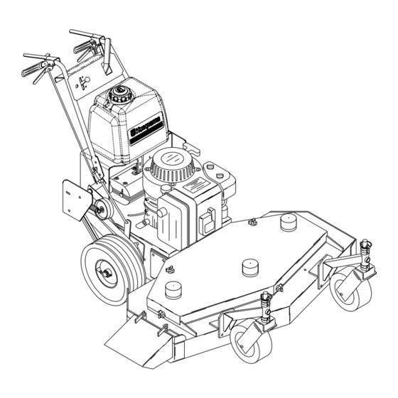
Summary of Contents for Husqvarna W3213
- Page 1 Operators manual Please read these instructions carefully and make sure you understand them before using the machine. MANUAL NO. 539106471 REV. 03 (08/23/04) Models: 968999114 / W3213 968999116 / W3613 968999251 / W4815 968999278 / WG4815P...
-
Page 2: Table Of Contents
Brake adjustment Operator presence switches Belt adjustments OPERATING INSTRUCTIONS : Emergency stopping Normal stopping Pre-start Operating instructions SERVICE : Interlock system Cutting deck Cutter housing Belt replacement Winter storage Maintenance chart © 2004 Husqvarna. All right reserved. Beatrice, NE. Printed U.S.A. - Page 3 BIRTH DEFECTS OR OTHER REPRODUCTIVE HARM. Thank you for buying an HUSQVARNA! Before operating your new mower, read, understand and follow the important safety instructions and the other instructions contained in this manual. Lawnmowers and all power equipment, can be potentially dangerous if used improperly. SAFETY REQUIRES GOOD JUDGEMENT,...
-
Page 4: Safety
Replace bag if loose seams or tears are evident. 5. Have your mower inspected and serviced each year by an authorized HUSQVARNA dealer. Determine if any additional devices are available which might upgrade the safety of your mower. -
Page 5: Axle Adjustment
Setup & Adjustments FRONT CASTER WHEELS 1. Mount front caster wheel assemblies. Installation includes fastening casters to front of the cutter deck using 3/8 x 1" hex head capscrews. FUEL TANK 1. Mount fuel tank to tank support. Secure with the two tank straps, four 1/4"... - Page 6 Setup & Adjustments REAR AXLE HEIGHT ADJUSTMENT AXLE PIVOT BOLTS AXLE ADJUSTMENT BOLTS POSITION A PLACE JACK HERE POSITION B POSITION C LOOSEN BOLTS EACH SIDE POSITION D Figure 1 CASTER HEIGHT ADJUSTMENT MACHINERY BUSHING 1/2" SPACERS CASTER SWIVEL Figure 2...
-
Page 7: Cutting Height Chart
Setup & Adjustments CUTTING HEIGHT ADJUSTMENT CHART NUMBER OF AXLE SPACERS BELOW POSITION CASTER ARM 1. To quickly achieve small changes in cutting heights, move the spacers from under the cutter housing to above the cutter pulley. (Each spacer moved will give an additional 1/4" of cutting height ). NUMBER OF 1/4"... -
Page 8: Brake/Traction Adjusment
Setup & Adjustments BRAKE / TRACTION ADJUSMENT 1. Disconnect the brake linkage from the brake band arm. 2. With the mower in gear, place the traction levers in the drive position. Firmly pull back on the handles until the tires slide to seat the wheel drive belts into the pulleys. - Page 9 TRANSMISSION DRIVE BELT To increase the tension of the transmission belt, loosen the nut on the underside of the transmission idler pulley located under the rear deck, slide the idler assembly inward to increase tension and tighten the nut to secure. See figure 4 & 5. BELT GUIDES Belt guides under rear deck are adjusted as shown in figure 4 &...
-
Page 10: Operating Instructions
Operating Instructions BEFORE OPERATING Be thoroughly familiar with all controls and how to use them before operating the mower. Know beforehand how to stop the engine, drive wheels, and mower blades in preparation for possible emergency. EMERGENCY STOP Pull both traction levers firmly against handle grips and hold them securely in place. -
Page 11: Operating Instructions
Operating Instructions 6. Pull starter rope until engine starts. 7. Warm engine momentarily, then move the throttle control out of the choke position until engine runs smoothly, approximately 1/2 throttle. Engage the blades and set the desired rpm. The best cutting and bagging is obtained with engine at or near top rpm. -
Page 12: Service
For the correct part or information for your particular mower, always mention model and serial number. We recommend returning your mower to an authorized HUSQVARNA dealer on a yearly basis for inspection and addition of any new devices which might upgrade the performance and safety of your mower. -
Page 13: Cutter Housing
CUTTER HOUSING SPINDLE ASSEMBLIES The cutter housing assembly is designed with a slip fit inner race and pulley. The sole purpose of the setscrew in the pulley is to hold the housing assem- bly together. The setscrew is not meant to secure the pulley. -
Page 14: Winter Storage
2. If friction washer is sticking - lubricate with Chemplex 710 silicone compound. WINTER STORAGE To prepare your Husqvarna mower for winter storage, perform the routine maintenance and necessary adjustments and record the part numbers of worn or broken parts so they may be ordered and replaced before the next mowing season. - Page 15 ITEM REAR TIRES FRONT TIRES UNDERSIDE OF MOWING DECK MOWER DECK UNDERSIDE OF REAR DECK BLADE PULLEYS ENGINE PULLEY FRONT WHEEL BEARINGS CASTER SHAFTS ENGINE OIL LEVEL REAR WHEELS BRAKE ARMS BLADE ENGAGEMENT BELLCRANK BLADE ENGAGEMENT FRICTION WASHER TRANSMISSION SHAFTS BLADES ENGINE AIR FILTER LINKAGES AND ADJUSTMENTS...


