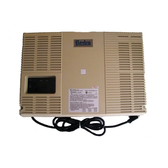
Summary of Contents for NEC Electra Professional
-
Page 5: Hardware Specifications
CHAPTER 1 HARDWARE SPECIFICATIONS AND INSTALLATION... - Page 6 Optional Key Telephone Units ....... . 1-9 1.7.5 Electra Elite Digital Multiline Terminals, Electra Professional Multiline Terminals, Single Line Telephones, and Associated Equipment ..1-10 1.7.6...
- Page 7 Installation Service Manual Electra Professional Level I June 1998 Cabling Requirements ..........1-14 2.4.1...
- Page 8 Installation Service Manual Electra Professional Level I June 1998 2.13.2 Multiline Terminal Flash Patterns Table......1-24 2.13.3 DSS/BLF LED Indications Table .
- Page 9 Installation Service Manual Electra Professional Level I June 1998 SECTION 5 INSTALLING A KEY TELEPHONE UNIT (KTU)....1-39 General Information..........1-39 5.1.1...
- Page 10 Line Card and Plastic Panel Installation ......1-65 Electra Professional Multiline Terminals....... 1-66 7.3.1...
- Page 11 Installation Service Manual Electra Professional Level I June 1998 SECTION 8 ANCILLARY DEVICE CONNECTION ......1-81 General Information..........1-81 Install the Electra Elite ADA-U Unit.
- Page 12 LIST OF FIGURES Outside View of the Electra Professional Level I KSU ......1-1 System Configuration Drawing (Example) ........1-6 System Block Diagram .
- Page 13 Installation Service Manual Electra Professional Level I June 1998 1-29 SMDR-C-10 KTU Switch Layout ........1-49 1-30 FAX-C(1)-11 KTU Installation.
- Page 14 Installation Service Manual Electra Professional Level I June 1998 1-58 Attaching the SLT-F(1G)-( ) ADP to the Wall ....... 1-73 1-59 Positioning the Handset Hanger .
- Page 15 Installation Service Manual Electra Professional Level I June 1998 1-87 Close the Tilt Panel Cover ..........1-93 1-88 Ferrite Core Installation .
- Page 16 Electra Professional Level I Terminals ........
- Page 131 CHAPTER 2 PROGRAMMING...
- Page 132 Installation Service Manual Electra Professional Level I June 1998 CHAPTER 2 PROGRAMMING TABLE OF CONTENTS SECTION 1 GENERAL ..........2-1 Introduction .
- Page 133 Installation Service Manual Electra Professional Level I June 1998 Memory Block LK 1 System Mode (continued) 1-03 Exclusive Hold Recall Timer Selection....... . 2-24 1-04 Internal/External Paging Access Time Selection .
- Page 134 Installation Service Manual Electra Professional Level I June 1998 Memory Block LK 1 System Mode (continued) 1-31 PBX/CTX Access Code Assignment ....... . . 2-52 1-32 Private Line Assignment .
- Page 135 Installation Service Manual Electra Professional Level I June 1998 Memory Block LK 1 System Mode (continued) 1-59 8-Digit Matching Table Trunk Group Assignment ..... . . 2-80 1-60 OCC Table Assignment .
- Page 136 Installation Service Manual Electra Professional Level I June 1998 Memory Block LK 3 CO/PBX Mode 3-10 CO Line Selection (Installed, DP, DTMF) ......2-107 3-11 Trunk-to-Trunk Group Assignment.
- Page 137 Installation Service Manual Electra Professional Level I June 1998 Memory Block LK 4 Telephone Mode 4-18 Doorphone Chime Assignment (Night Mode) ......2-134 4-19 Station to Class of Service Feature Assignment (Day Mode) .
- Page 138 Installation Service Manual Electra Professional Level I June 1998 Code Restriction Tables ......... . . 2-161 7.5.1...
- Page 139 Electra Elite Multiline Terminal ........2-5 Electra Professional Level I System Multiline Terminal....2-6...
-
Page 310: System Maintenance
CHAPTER 3 SYSTEM MAINTENANCE... - Page 311 Installation Service Manual Electra Professional Level I June 1998 CHAPTER 3 SYSTEM MAINTENANCE TABLE OF CONTENTS SECTION 1 INTRODUCTION ......... . . 3-1 SECTION 2 OPERATIONAL CURRENT AND VOLTAGE CHECKS .
- Page 312 Installation Service Manual Electra Professional Level I June 1998 No Dial Access to Features on SLT........3-16 Low Volume Problems.
- Page 333 CHAPTER 4 ELECTRA ELITE TERMINAL UPGRADE...
- Page 334 Installation Service Manual Electra Professional Level I June 1998 CHAPTER 4 ELECTRA ELITE TERMINAL UPGRADE TABLE OF CONTENTS COMPARISONS............4-1 POWER REQUIREMENTS .
- Page 335 Installation Service Manual Electra Professional Level I June 1998 LIST OF FIGURES Figure 4-1 Electra Elite Multiline Terminals ........4-4 Figure 4-2 Removing the Tilt Panel on the Multiline Terminal .
- Page 336 Installation Service Manual Electra Professional Level I June 1998 LIST OF FIGURES Continued Figure 4-29 Removing the Tabs from the Adapter ....... . . 4-23 Figure 4-30 Removing the Tabs from the WMU-U Unit .
- Page 337 Installation Service Manual Electra Professional Level I June 1998 LIST OF TABLES Table 4-1 Multiline Terminal Loop Resistance and Cable Length ....4-2 Table 4-2 ADA-U Cable Connections .
-
Page 364: Features And Specifications
CHAPTER 5 SERIES 500 FEATURES AND SPECIFICATIONS... - Page 365 Installation Service Manual Electra Professional Level I June 1998 CHAPTER 5 SERIES 500 FEATURES AND SPECIFICATIONS SECTION 1 INTRODUCTION ......... . . 5-1 SECTION 2 FEATURES .


