Sign In
Upload
Manuals
Brands
ABB Manuals
DC Drives
ACS880-07C
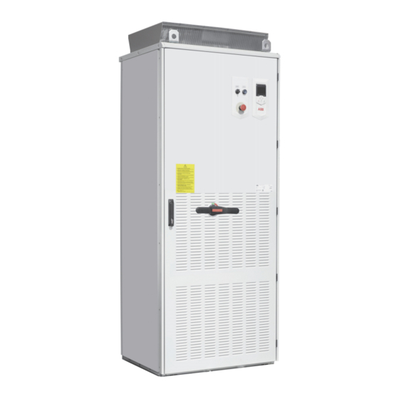
ABB ACS880-07C Manuals
Manuals and User Guides for ABB ACS880-07C. We have
1
ABB ACS880-07C manual available for free PDF download: Hardware Manual
ABB ACS880-07C Hardware Manual (188 pages)
Brand:
ABB
| Category:
DC Drives
| Size: 60.38 MB
Table of Contents
Table of Contents
5
Safety Instructions
13
Contents of this Chapter
13
Use of Warnings
13
General Safety in Installation, Start-Up and Maintenance
14
Electrical Safety in Installation, Start-Up and Maintenance
16
Precautions before Electrical Work
16
Additional Instructions and Notes
17
Grounding
19
Additional Instructions for Permanent Magnet Motor Drives
20
Safety in Installation, Start-Up and Maintenance
20
Introduction to the Manual
21
Contents of this Chapter
21
Target Audience
21
Contents of the Manual
21
Related Manuals
22
Categorization by Frame Size and Option Code
22
Quick Installation, Start-Up and Operating Flowchart
22
Terms and Abbreviations
23
Operation Principle and Hardware Description
25
Contents of this Chapter
25
Product Overview
25
Single-Line Circuit Diagram of the Drive
26
Block Diagram of the Brake and DC Options (+D150)
27
General Information on the Cabinet Layout
28
Cabinet Layout of Frames R6 to R9
29
Cabinet Layout of Frames R10 to R11
30
Overview of Power and Control Connections
31
Door Switches and Lights
33
Main Switch-Disconnector Q1
33
Control Panel
34
Control by PC Tools
34
Descriptions of Cabinet Options
34
Degree of Protection
34
Definitions
34
Ip22
34
IP42 (Option +B054)
35
Resistor Braking (Options +D150)
35
EMC Filters (Options + E200)
35
Du/Dt Filter (Option +E205)
35
Common Mode Filter (Option +E208)
35
Cabinet Heater with External Supply (Option +G300)
35
Terminals for External Uninterruptible Control Voltage (Option +G307)
35
Additional Terminal Block X504 (Option +L504)
36
Thermistor Relays (Options +L505, +2L505)
36
Pt100 Relays (Options +3L506, +5L506, +8L506)
37
What the Option Contains
37
Description
37
Type Designation Label
37
Type Designation Key
38
Mechanical Installation
41
Contents of this Chapter
41
Examining the Installation Site
41
Necessary Tools
42
Moving and Unpacking the Drive
43
Unpacking the Transport Package
44
Checking the Delivery
44
Moving the Drive Cabinet
44
Fastening the Cabinet to the Floor
45
General Rules
45
Fastening Methods
46
Alternative 1 - Clamping
46
Alternative 2 - Using the Holes Inside the Cabinet
46
Miscellaneous
47
Cable Duct in the Floor below the Cabinet
47
Arc Welding
48
Guidelines for Planning the Electrical Installation
49
Contents of this Chapter
49
Limitation of Liability
49
Selecting the Supply Disconnecting Device
49
Selecting the Main Contactor
49
Examining the Compatibility of the Motor and Drive
50
Protecting the Motor Insulation and Bearings
50
Requirements Table
51
Additional Requirements for ABB Motors of Types Other than M2_, M3_, M4_, HX_ and
53
Additional Requirements for the Braking Applications
53
Additional Requirements for ABB High-Output and IP23 Motors
53
Additional Requirements for Non-ABB High-Output and IP23 Motors
54
Additional Data for Calculating the Rise Time and the Peak Line-To-Line Voltage
55
Additional Note for Sine Filters
55
Selecting the Power Cables
56
General Rules
56
Typical Power Cable Sizes
57
Alternative Power Cable Types
58
Recommended Power Cable Types
58
Power Cable Types for Limited Use
58
Not Allowed Power Cable Types
58
Motor Cable Shield
58
Planning the Braking System
59
Selecting the Control Cables
59
Shielding
59
Signals in Separate Cables
59
Signals Allowed to be Run in the same Cable
59
Relay Cable Type
59
Control Panel Cable Length and Type
59
Routing the Cables
59
Separate Control Cable Ducts
60
Continuous Motor Cable Shield or Enclosure for Equipment on the Motor Cable
60
Implementing Thermal Overload and Short-Circuit Protection
61
Protecting the Drive and Input Power Cable in Short-Circuits
61
Protecting the Motor and Motor Cable in Short-Circuits
61
Protecting the Drive and the Input Power and Motor Cables against Thermal Overload
62
Protecting the Motor against Thermal Overload
62
Protecting the Drive against Ground Faults
62
Residual Current Device Compatibility
62
Implementing the Emergency Stop Function
62
Implementing the Safe Torque off Function
63
Implementing the Power-Loss Ride-Through Function
63
Units with Main Contactor (Option +F250)
63
Supplying Power for the Auxiliary Circuits
63
Using Power Factor Compensation Capacitors with the Drive
63
Implementing a Safety Switch between the Drive and the Motor
64
Using a Contactor between the Drive and the Motor
64
Implementing a Bypass Connection
65
Protecting the Contacts of Relay Outputs
65
Connecting a Motor Temperature Sensor to the Drive I/O
66
Electrical Installation
67
Contents of this Chapter
67
Warnings
67
Checking the Insulation of the Assembly
67
Drive
67
Input Cable
67
Motor and Motor Cable
68
Brake Resistor Assembly
68
Checking the Compatibility with Grounded Systems
68
Connecting the Power Cables
70
Connection Diagram
70
Layout of the Power Cable Connection Terminals and Lead-Throughs (Frames R6 to R9)
71
Layout of the Power Cable Connection Terminals and Lead-Throughs (Frames R10 to R11)
72
Lead-Through of External Resistor and DC Cables
73
Connection Procedure (IEC)
73
Grounding the Motor Cable Shield at the Motor End
75
Connecting the Control Cables
75
Control Cable Connection Procedure
75
Grounding the Outer Shields of the Control Cables at the Cabinet Lead-Through
76
Routing the Control Cables Inside the Cabinet (Frames R6 to R9)
78
Routing the Control Cables Inside the Cabinet (Frames R10 and R11)
79
Connecting the External 230 V Uninterruptible Control Voltage (UPS, Option +G307)
81
Connecting the Emergency Stop Push Buttons
81
Q964)
81
Wiring the Starter for Auxiliary Motor Fan (Options +M600
81
Wiring the Thermistor Relay(S) (Options +L505 and +2L505)
82
Wiring the Pt100 Relays (Options +2L506, +3L506, +5L506 and +8L506)
83
Connecting the External Power Supply Cables for the Cabinet Heater and Lighting and Motor Heater (Options +G300, +G301)
84
Connecting a PC
85
Setting the Voltage Range of the Auxiliary Control Voltage Transformer (T21)
86
Installing Option Modules
87
Mechanical Installation of I/O Extension, Fieldbus Adapter and Pulse Encoder Interface
87
Modules
87
Wiring I/O Extension, Fieldbus Adapter and Pulse Encoder Interface Modules
87
Control Unit of Frames R6 to R9
89
Contents of this Chapter
89
Layout
90
Default I/O Connection Diagram of Frames R6 to R9
91
Notes
92
Jumpers and Switches
92
External Power Supply for the Control Unit
92
AI1 and AI2 as Pt100, Pt1000, PTC and KTY84 Sensor Inputs (XAI, XAO)
93
DI6 (XDI:6) as PTC Sensor Input
94
DIIL Input (XD24:1)
94
Drive-To-Drive Link (XD2D)
94
Safe Torque off (XSTO)
95
Technical Data
95
Control Unit of Frames R10 and R11
99
Contents of this Chapter
99
Layout
100
Default I/O Connection Diagram of Frames R10 and R11
101
Notes
102
Drive-To-Drive Link (XD2D)
102
Ground Isolation Diagram
104
Installation Checklist
105
Contents of this Chapter
105
Warnings
105
Checklist
105
Start-Up
107
Contents of this Chapter
107
Start-Up Procedure
107
Checks/Settings with no Voltage Connected
107
Powering up the Drive
107
Setting up the Drive Parameters, and Performing the First Start
108
On-Load Checks
108
Fault Tracing
109
Contents of this Chapter
109
Leds
109
Warning and Fault Messages
109
Maintenance
111
Contents of this Chapter
111
Maintenance Intervals
111
Descriptions of Symbols
111
Recommended Annual Maintenance Actions by the User
111
Recommended Maintenance Intervals after Start-Up
112
Cleaning the Interior of the Cabinet
113
Heatsink
113
Fans
113
Replacing the Cabinet Fans (Frames R6 to R9)
114
Replacing the Cabinet Fans (Frames R10 to R11)
115
Replacing the Drive Module Main Fans (Frames R6 to R8)
116
Replacing the Auxiliary Cooling Fan of the Drive Module (Frames R6 to R9)
117
Replacing the Drive Module Main Fans (Frame R9)
118
Replacing the Drive Module Main Fans (Frames R10 and R11)
119
Replacing the Circuit Board Compartment Cooling Fan (Frames R10 and R11)
122
Replacing the Drive Module (Frames R6 to R9)
123
Replacing the Drive Module (Frames R10 and R11)
127
Capacitors
133
Reforming the Capacitors
133
Replacing the Control Panel Battery
134
Replacing the Control Unit Battery
134
Memory Unit
134
Transferring the Memory Unit
135
Technical Data
137
Contents of this Chapter
137
Ratings
137
Definitions
138
Derating
139
Ambient Temperature Derating
139
Altitude Derating
140
Deratings for Special Settings in the Drive Control Program
140
Low Noise
140
High Speed Mode
142
Low Noise Mode Derating
143
Dimensions and Weights
145
Free Space Requirements
145
Losses, Cooling Data and Noise
146
Terminal and Lead-Through Data for the Power Cables
146
IEC - Standard Configuration
146
IEC - Option +E205
147
R6: Input and Output Cable Terminal Size (Incoming Switch OT160)
148
R7: Input and Output Cable Terminal Size (Incoming Switch OT160/OT250)
149
R8: Input and Output Cable Terminal Size (Incoming Switch OT160/OT250)
150
R7: Input and Output Cable Terminal Size (Incoming Switch OT315)
151
R8: Input and Output Cable Terminal Size (Incoming Switch OT315)
152
R9: Input and Output Cable Terminal Size (Incoming Switch OT315/OT400)
153
R9: Input and Output Cable Terminal Size (Incoming Switch OT630)
154
R7/R8: Input Cable Terminal Size (Incoming Switch OT315, Option +F250)
156
R9: Input Cable Terminal Size (Incoming Switch OT315/OT400, Option +F250)
157
R9: Input Cable Terminal Size (Incoming Switch OT630, Option +F250)
158
R6/ R7/R8: Output Cable Terminal Size (DU/DT Filter, Option +E205)
159
R9: Output Cable Terminal Size (DU/DT Filter, Option +E205)
160
R10: Input and Output Cable Terminal Size
161
R11: Input and Output Cable Terminal Size
164
Terminal Data for the Control Cables
167
Electrical Power Network Specification
167
Motor Connection Data
167
Control Unit Connection Data
167
Efficiency
167
Protection Classes
168
Ambient Conditions
168
Auxiliary Circuit Power Consumption
168
Compliance with the en 61800-3:2004
169
Definitions
169
Materials
169
Applicable Standards
169
Category C3
170
Category C4
170
Cyber Security Disclaimer
171
Disclaimer
171
Dimension Drawings
173
Frame Sizes R6 to R8
174
Frame Size R9
175
Frame Size R10
176
Frame Size R11
177
Safe Torque off Function
179
Contents of this Chapter
179
Resistor Braking
181
Contents of this Chapter
181
Operation Principle and Hardware Description
181
Planning the Braking System
181
Selecting the Brake Circuit Components
181
Selecting a Custom Resistor
182
Selecting and Routing the External Brake Resistor Cables
182
Minimizing Electromagnetic Interference
182
Maximum Cable Length
183
EMC Compliance of the Complete Installation
183
Placing the Brake Resistors
183
Protecting the System against Thermal Overload
183
Protecting the Resistor Cable against Short-Circuits
183
Mechanical Installation of External Brake Resistors
184
Electrical Installation
184
Checking the Insulation of the Assembly
184
Connection Diagram
184
Connection Procedure
184
Start-Up
184
Technical Data
185
Ratings
185
Terminals and Cable Lead-Through Data
186
Further Information
187
Product and Service Inquiries
187
Product Training
187
Providing Feedback on ABB Drives Manuals
187
Document Library on the Internet
187
Advertisement
Advertisement
Related Products
ABB ACS880-07C-0105A-3
ABB ACS880-07C-0145A-3
ABB ACS880-07C-0169A-3
ABB ACS880-07C-0206A-3
ABB ACS880-07C-0246A-3
ABB ACS880-07C-0293A-3
ABB ACS880-07C-0363A-3
ABB ACS880-07C-0430A-3
ABB ACS880-07C-0505A-3
ABB ACS880-07C-0585A-3
ABB Categories
Industrial Equipment
Controller
Measuring Instruments
Battery Charger
DC Drives
More ABB Manuals
Login
Sign In
OR
Sign in with Facebook
Sign in with Google
Upload manual
Upload from disk
Upload from URL