Sign In
Upload
Manuals
Brands
ABB Manuals
Inverter
PVS-100 Series
ABB PVS-100 Series String Inverter Manuals
Manuals and User Guides for ABB PVS-100 Series String Inverter. We have
3
ABB PVS-100 Series String Inverter manuals available for free PDF download: Product Manual, Hardware Manual
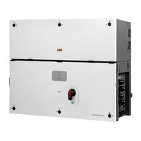
ABB PVS-100 Series Product Manual (171 pages)
100 to 120 kW
Brand:
ABB
| Category:
Inverter
| Size: 29.69 MB
Table of Contents
Ntroduction and General Information
4
Warranty and Supply Conditions
4
Not Included in the Supply
4
Table of Contents
5
Scope and Target Audience
9
Purpose and Document Structure
9
List of Appendix Documents
9
Operator and Maintenance Personnel Skills/Prerequisites
9
Symbols and Signs
10
Field of Use, General Conditions
12
Intended or Allowed Use
12
Limits in Field of Use
12
Improper or Prohibited Use
12
Haracteristics
13
General Conditions
13
Identification of the Equipment and Manufacturer
14
Models and Range of Equipment
16
List of Main Reference Components
17
Communication Board
17
Characteristics and Technical Data
19
Tightening Torques
21
Cable Gland Clamping Range
21
Overall Dimensions
22
Mounting Bracket
22
Efficiency Curves
23
Power Limitation (Power Derating)
24
Power Reduction Due to Environmental Conditions
25
Power Reduction Due to the Input Voltage
26
P- Q Curve Capability
27
Characteristics of a Photovoltaic Generator
28
Strings and Arrays
28
Description of the Equipment
29
Operating Diagram (Example)
29
Mutual Connection of Multiple Inverters
30
Notes on the System Sizing
30
Functionality and Components of the Equipment
31
Highlights
31
Improved Commissioning and Maintenance
31
Aurora Vision ® Plant Management Platform
32
Configurable Relays
33
Remote Switch-On/Switch-Off
33
Reactive Power Feed into the Grid
33
Limiting the Active Power Fed into the Grid
33
Overvoltage Surge Arrester Monitoring
33
Data Transmission and Control
33
Communication Connection Diagrams
34
Communication Interface
34
Ethernet Bus Connection
34
Topographic Diagram of the Equipment
36
Safety Devices
38
Anti-Islanding
38
Ground Fault of the Photovoltaic Panels
38
String Fuses
38
Overvoltage Surge Arresters
38
Other Safeguards
38
Afety and Accident Prevention
39
Safety Information and Instructions
39
Hazardous Areas and Operations
40
Environmental Conditions and Risks
40
Signs and Labels
40
Thermal and Electrical Hazard
41
Clothing and Protection of Personnel
41
Residual Risks
42
Table of Residual Risks
42
Ifting and Transport
43
General Conditions
43
Transport and Handling
43
Lifting
43
Unpacking and Checking
43
Storage
44
Weight of the Modules of the Equipment
44
Types of Lifting
45
List of Components Supplied
47
Kit of Recommended Spare Parts
48
Nstallation
49
General Conditions
49
Installation Site and Position
50
Wireless Signal Environmental Checks
53
Installations above 2000 Metres
54
Installations with a High Level of Humidity
54
Installations of IP66 Protection Covers for Wiring Box Openings (Long Term Installation)
55
Mounting with a Support Bracket
56
Routing the Cable to the Inverter
68
Grid Output Connection (AC Side)
69
Characteristics and Sizing of the Protective Grounding Cable
69
Characteristics and Sizing of the Line Cable
70
Load Protection Switch (AC Disconnect Switch)
70
Selection of Differential Protection Downstream of the Inverter
71
AC Output Cables Connection
72
Operations Preliminary to the Connection of the PV Generator
75
Checking of Leakage to Ground of the Photovoltaic Generator
75
Checking of Strings Voltage
75
Checking the Correct Polarity of the Strings and Fuses Installation
76
Input Connection to PV Generator (DC Side)
77
Installation Procedure for Quick-Fit Connectors
79
String Protection Fuses
83
Sizing of Fuses
83
Access the Negative Side String Fuses Board
85
(-SX2, SY2 Wiring Box Version Only)
85
Communication and Control Board
86
Connections to the Communication and Control Board
87
Ethernet Connection
88
Serial Communication Connection (RS485 - Slave Mode)
90
Serial Communication Connection (RS485 - Master Mode)
94
Remote Control Connection
95
Demand Response Mode 0 (AS/NZS 4777.2)
95
Configurable Relay Connection (ALARM and AUX)
96
Nstruments
97
General Conditions
97
Description of the LED Function
98
User Interface
99
Measurement Tolerance
99
Peration
100
General Conditions
100
Commissioning
101
Commissioning Via ABB Installer for Solar Inverters Mobile APP
102
Commissioning Via Web UI - Wireless Connection
104
Power, Alarm, GFI Leds Behaviour
112
COMM. (WI-FI/ETHERNET) LED Behaviour
114
Description of the Web User Interface
115
Access to the Web User Interface
115
Web User Interface Menu Structure
118
MAIN Section
119
SETUP Section
121
EVENTS Section
125
USER Section
126
NETWORK Section
127
TOOLS Section
134
INFORMATION Section
137
Inverter Switch-Off
138
Operator and Maintenance Personnel Skills/Prerequisites
138
Switch-Off Procedure
139
Aintenance
145
General Conditions
145
Routine Maintenance
146
Troubleshooting
147
Web User Interface and Wireless Communication Troubleshooting
147
Alarm Messages of the Inverter
149
Power Limitation Messages
156
Registration on "Registration" Website and Calculation of Security Token (Admin Plus)
157
Registration on “Registration” Website and Calculation of Security Token (Admin Plus)
160
Procedure for Dismantling the Inverter and Wiring Box
160
Replacing DC String Fuses
161
Replacing Cooling Section
162
Replacement of the Buffer Battery
163
Verification of Ground Leakage
164
Behaviour of a System Without Leakage
164
Behaviour of a System with Leakage
165
Measuring the Isolation Resistance of the PV Generator
166
Storage and Dismantling
167
Storage of the Equipment or Prolonged Stop
167
Dismantling, Decommissioning and Disposal
167
Ttachments
168
Port and Network Services Used by the Inverter
168
IP Network Services
168
Network Hosts
169
Inverter Network Configuration
169
Further Information
170
Contact Us
171
Advertisement
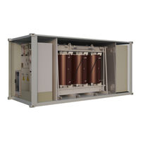
ABB PVS-100 Series Hardware Manual (74 pages)
Medium voltage station
Brand:
ABB
| Category:
Inverter
| Size: 5.35 MB
Table of Contents
Table of Contents
5
1 Safety Instructions
9
Contents of this Chapter
9
Use of Warnings
9
Allowed Usage
10
Safe Installation, Start-Up and Maintenance
10
General Safety Instructions
10
MVS Working Area Safety
11
Personal Protective Equipment (PPE)
11
Safety Instructions for MV Switchgear and MV Transformer Area
11
Safety Instructions for the Auxiliary Services Board
12
Safe Operation
13
2 Hardware Description
15
Contents of this Chapter
15
Product Overview
15
External Dimensions
15
Layout Drawing
16
Working Areas and Main Components
16
Main Components
17
AC Cabinet Components
18
Inverter Inputs
18
Auxiliary Service Board
19
MV Switchgear
20
MV Switchgear Circuit
20
MV Transformer
21
String Inverter
22
Main Circuit Diagram
22
Type Designation Label
23
Type Designation Key
24
MVS Optional Codes
24
3 Storing, Lifting and Transporting
27
Contents of this Chapter
27
Storing
28
Conditions for Using Desiccant Bags
28
Lifting
29
Tools Used for Lifting
29
Lifting Instructions
30
Transporting
30
Incoming Inspection at Arrival
31
4 Mechanical Installation
33
Contents of this Chapter
33
Safety
33
Tools
33
Foundation Guidelines
33
Placing the MVS on the Foundation
34
Fastening the MVS
35
Constructing Earthing Electrode and Earthing
35
Filling the Pit and Finalizing the Surroundings
36
Adding Weather Protection Hoods
37
Tools
37
Procedure
38
5 Electrical Installation
41
Contents of this Chapter
41
Routing the Cables
42
Earthing
42
Protective Earthing (Grounding) Inside the MVS
43
Measuring the Insulation Resistance of the Cabling
43
Connecting the Inverter Inputs
44
Connecting the Communication and Auxiliary Cabling (Optional)
46
Connecting the Power Grid Cabling to the MV Switchgear
46
6 Finalizing the Installation
49
Contents of this Chapter
49
Landscaping the Station
50
Checking the Installation of MVS
50
7 Start-Up and Operation
51
Contents of this Chapter
51
Tools Needed
51
Prerequisite
51
Start-Up Procedure
52
8 Maintenance
55
Contents of this Chapter
55
Tools List
55
Tightening Torque
56
Maintenance Intervals
57
Maintenance Activities
57
Maintenance Intervals
58
Cleaning Procedure
58
Replacing Component
60
Maintenance of Painted Surfaces
62
Repainting the Scratched Areas
62
Tools and Materials
62
Painting the Damaged Surface (no Visible Rust)
62
Painting the Damaged Surface (Visible Rust)
62
Maintenance of Zinc Coated Surfaces
63
Maintenance of Grounding Bars and Points
63
Tools
63
Procedure
63
Maintaining External Hinges and Locks
63
Replacing the Door Limit Switch
64
9 Technical Data
65
Contents of this Chapter
65
Technical Data and Types: PVS-100 MVS
66
Technical Data and Types: PVS-120 MVCS
68
10 Drawings
71
Contents of this Chapter
71
List of Technical Drawings
71
Further Information
73
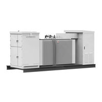
ABB PVS-100 Series Hardware Manual (70 pages)
Solar Inverters Medium Voltage Compact Skid
Brand:
ABB
| Category:
Inverter
| Size: 5.24 MB
Table of Contents
Table of Contents
5
1 Safety Instructions
9
Contents of this Chapter
9
Use of Warnings
9
Allowed Usage
10
Safe Installation, Start-Up and Maintenance
10
General Safety Instructions
10
MVCS Working Area Safety
11
Personal Protective Equipment (PPE)
11
Safety Instructions for MV Switchgear and MV Transformer Area
11
Safety Instructions for the Auxiliary Services Board
12
Safe Operation
13
2 Introduction to this Manual
15
Contents of this Chapter
15
Applicability
15
Target Audience
15
Related Documents
15
Terms and Abbreviations
16
3 Hardware Description
17
Contents of this Chapter
17
Product Overview
17
External Dimensions
17
Layout Drawing
18
Working Areas and Main Components
18
Main Components
19
AC Cabinet Components
20
Inverter Inputs
20
Auxiliary Service Board
20
MV Switchgear
22
MV Switchgear Circuit
22
MV Transformer
23
String Inverter
24
Main Circuit Diagram
24
Type Designation Label
25
Type Designation Key
26
MVCS Optional Codes
26
4 Storing, Lifting and Transporting
29
Contents of this Chapter
29
Storing
30
Conditions for Using Desiccant Bags
30
Lifting
31
Tools Used for Lifting
31
Lifting Instructions
32
Transporting
33
Incoming Inspection at Arrival
33
Unloading
34
Tools Used for Unloading
34
Unloading Instructions
35
5 Mechanical Installation
37
Contents of this Chapter
37
Safety
37
Tools
37
Foundation Guidelines
37
Placing the MVCS on the Foundation
38
Fastening the MVCS
39
Constructing Earthing Electrode and Earthing
39
Filling the Pit and Finalizing the Surroundings
40
6 Electrical Installation
41
Contents of this Chapter
41
Routing the Cables
42
Earthing
42
Protective Earthing (Grounding) Inside the MVCS
42
Measuring the Insulation Resistance of the Cabling
42
Connecting the Inverter Inputs
43
Connecting the Communication and Auxiliary Cabling (Optional)
45
Connecting the Power Grid Cabling to the MV Switchgear
45
7 Finalizing the Installation
47
Contents of this Chapter
47
Landscaping the Station
48
Checking the Installation of MVCS
48
8 Start-Up and Operation
49
Contents of this Chapter
49
Tools Needed
49
Prerequisite
49
Start-Up Procedure
50
9 Maintenance
53
Contents of this Chapter
53
Tools List
53
Tightening Torque
54
Maintenance Intervals
55
Maintenance Activities
55
Maintenance Intervals
56
Cleaning Procedure
56
Maintenance of Painted Surfaces
57
Repainting the Scratched Areas
57
Tools and Materials
57
Painting the Damaged Surface (no Visible Rust)
58
Painting the Damaged Surface (Visible Rust)
58
Maintenance of Zinc Coated Surfaces
58
Maintenance of Grounding Bars and Points
58
Tools
58
Procedure
59
10 Technical Data
61
Contents of this Chapter
61
Technical Data and Types: PVS-100 MVCS
62
Technical Data and Types: PVS-120 MVCS
64
11 Drawings
67
Contents of this Chapter
67
List of Technical Drawings
67
Further Information
69
Advertisement
Advertisement
Related Products
ABB PVS-100-TL
ABB PVS-100-TL-800
ABB PVS-100-TL-1000
ABB PVS-100-TL-1200
ABB PVS-100-TL-1400
ABB PVS-100-TL-1800
ABB PVS-100-TL-1600
ABB PVS-100-TL-2200
ABB PVS-100-TL-2000
ABB PVS-100-TL-2400
ABB Categories
Industrial Equipment
Controller
Measuring Instruments
Battery Charger
DC Drives
More ABB Manuals
Login
Sign In
OR
Sign in with Facebook
Sign in with Google
Upload manual
Upload from disk
Upload from URL