Sign In
Upload
Manuals
Brands
Canon Manuals
All in One Printer
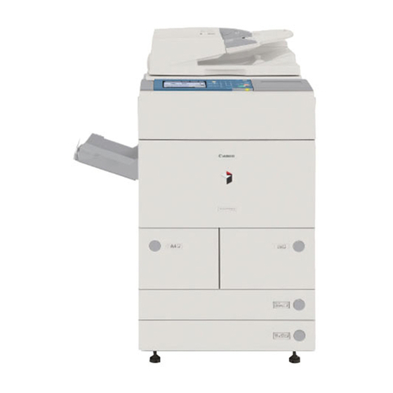
imageRUNNER 5065 series
Canon imageRUNNER 5065 series Manuals
Manuals and User Guides for Canon imageRUNNER 5065 series. We have
1
Canon imageRUNNER 5065 series manual available for free PDF download: Service Manual
Canon imageRUNNER 5065 series Service Manual (596 pages)
Brand:
Canon
| Category:
All in One Printer
| Size: 27.8 MB
Table of Contents
Table of Contents
7
Internal Delivery Roller
18
Periodically Replaced Parts
22
Table of Contents
22
Table of Contents
29
Chapter 1 Introduction
31
System Construction
31
Functions and Printing/Transmission Accessories (230V)
32
Product Specifications
33
Cross-Section
34
Using the Machine
36
Control Panel
38
User Mode Items
38
Common Settings
38
Timer Settings
39
Adjustment/Cleaning
39
Report Output
39
System Control Settings
40
Copier Specifications
41
Transmission/Reception Settings
42
Box Settings
43
Printer Settings
43
Address Book Settings
44
Voice Guide Settings
45
Maintenance by the User
45
Cleaning
45
Checks
46
Safety
47
Safety of the Machine's Laser Unit
47
CDRH Regulations
47
Handling the Machine's Laser Unit
48
Safety of Toner
48
Product Specifications
48
Function List
50
Paper Types
50
Printing Speed
50
Paper Types/Printing Speed (K Paper)
51
Table of Contents
55
Chapter 2 Selecting the Installation Space
57
Combination Table of Accessories
58
Checking the Contents
59
Making Pre-Checks
57
Unpacking and Installation
61
Unpacking and Installation Procedure
61
Unpacking
61
Installation of Scanner
62
Installation of Fixing Assembly
62
Checking of Charging Assembly and Dustproof Glass
63
Installation of Developing Assembly
65
Installation of Pickup Assembly
65
Attaching Deck Pressure Plate
66
Setting Toner Container
66
Connecting the Cable
66
Checking the Environment Switch
67
Attaching the Label
67
Connecting the Power Cord
68
Turning on the Main Power Switch
68
Toner Stirring
68
Media Cassette Settings
68
Index Paper Attachment
69
Changing the Media Size of the Front Deck (Left/Right)
69
Image/Operation Check in User Mode
69
Adjustment of Image Left End Margin
69
Adjustment of Image Leading Edge Margin
71
Mounting of the Host Machine
71
Checking the Connection to the Network
73
Overview
73
Using the Ping Command
73
Making a Check Using the Remote Host Address
73
Troubleshooting the Network
74
Checking the Connection of the Network Cable
74
Making a Check Using a Loopback Address
74
Making a Check Using a Local Host Address
74
Installing the Card Reader
74
Notice at Installation
74
Confirming the Contents
74
Power off of the Host Machine
75
Installation Procedure
75
Installing for Imageware Accounting Manager
77
Installing the Original Holder
78
Checking Contents
78
Installation Procedure
78
Checking Contents
79
Installation Procedure
79
Installing the Reader Heater
80
Checking the Contents
80
Power off of the Host Machine
80
Installation Procedure
80
Installing the Cassette Heater
84
Checking Components
84
Power off of the Host Machine
84
Installation Procedure of the Cassette Heater
84
Installing the Deck Heater
89
Checking the Parts to Install
89
Turning off the Host Machine
90
Installing the Deck Heater (Large Deck)
90
Checking the Parts to Install
90
Turning off the Host Machine
91
Installing the Voice Guidance Kit
91
A Point to Keep in Mind at Installation
91
Checking the Contents
91
Power off of the Host Machine
92
Installation Procedure
92
Construction/Basic Sequence
101
Construction
103
Functional Construction
103
Wiring Diagram of the Major Pcbs
103
Controlling the Main Motor (M2)
104
Basic Sequence
105
Basic Sequence of Operation (at Power-On; 30-Sec Start-Up Mode)
105
Basic Sequence of Operation (at Power-On; Low-Temperature Start-Up Mode)
105
Basic Sequence of Operation (at Power-On; High-Humidity Start-Up Mode)
106
Basic Sequence of Operation (at Time of Copying/Printing)
107
Table of Contents
111
Construction
113
Construction and Mechanisms
113
Construction of the Electrical Circuitry
113
Main Controller PCB
113
Hdd
115
Start-Up Sequence
116
Overview
116
Image Processing
118
Overview of the Image Flow
118
Construction of the Image Processing Module
119
Reader Unit Input Image Processing
119
Compression/ Extension/ Editing Block
120
Printer Unit Output Image Processing
120
Shut-Down Sequence
118
Overview
118
Flow of Operation
118
Flow of Image Data
121
Flow of Image Data According to Copy Functions
121
Flow of Image Data for the Box Function
121
Flow of Image Data for the SEND Function
122
Flow of Image Data for the Fax Transmission
122
Flow of Image Data for the Fax Reception Function
123
Flow of Image Data for the PDL Function
123
Parts Replacement Procedure
125
Main Controller Box
125
Before Removing the Main Controller Box
125
Removing the Main Controller Box
125
Main Controller PCB
125
Before Removing the Main Controller PCB
125
Removing the Main Controller PCB
125
When Replacing the Main Controller PCB
126
Sdram
126
Before Removing the SDRAM
126
Removing the SDRAM
126
Boot ROM
126
Before Removing the Boot ROM
126
Removing the Boot ROM
126
Hdd
127
Before Removing HDD
127
Removing the HDD
127
After Replacing the HDD
127
Video PCB
127
Before Removing the Video PCB
127
Removing the Video PCB
127
Controller Fan
128
Before Removing the Controller Cooling Fan
128
Removing the Controller Cooling Fan
128
Table of Contents
131
Construction
133
Specifications, Controls, and Functions
133
Major Components
133
Reader Controller PCB
133
Construction of the Control System
134
Reader Controller PCB
135
Basic Sequence
136
Basic Sequence of Operations
136
Basic Sequence of Operation in Response to a Press on the Start Key
137
Various Control
137
Controlling the Scanner Drive System
137
Overview
137
Controlling the Scanner Motor
138
Enlargement/Reduction
138
Changing the Magnification in Main Scanning Direction
138
Changing the Magnification in Sub Scanning Direction
138
Controlling the Scanning Lamp
139
Overview
139
Scanning Lamp
140
Controlling the Activation
140
Detecting the Size of Originals
140
Overview
140
Points of Measurement Used for Original Size Identification
140
Overview of Operation
141
Dirt Sensor Control
143
Dust Detection in Stream Reading Mode
143
White Plate Dust Detection Control
144
Image Processing
145
Overview
145
CCD Drive
146
CCD Output Gain Correction, Offset Correction
146
CCD Output A/D Conversion
146
Outline of Shading Correction
146
Shading Adjustment
147
Shading Correction
147
Parts Replacement Procedure
148
CCD Unit
148
Before Removing the CCD Unit
148
Removing the CCD Unit
148
When Replacing the CCD Unit
148
Copyboard Glass
149
Removing the Copyboard Glass
149
When Replacing the Copyboard Glass
149
Scanning Lamp
149
Before Removing the Scanning Lamp
149
Removing the Scanning Lamp
149
When Replacing the Scanning Lamp
150
Reader Controller PCB
150
Before Removing the Reader Controller PCB
150
Removing the Reader Controller PCB
150
After Replacing the Reader Controller PCB
151
Interface PCB
151
Before Removing the Interface PCB
151
Removing the Interface PCB
151
Inverter PCB
152
After Replacing the Inverter PCB
153
Memory PCB
152
Scanner Motor
153
Before Removing the Scanner Motor
153
Removing the Scanner Motor
153
Mounting the Scanner Motor
154
ADF Open/Close Sensor
154
Before Removing the ADF Open/Close Sensor
154
Removing the ADF Open/Close Sensor
154
Scanner HP Sensor
154
Before Removing the Scanner HP Sensor
154
Removing the Mirror Base HP Sensor
154
Original Size Sensor
155
Before Removing the Original Size Sensor
155
Removing the Original Size Sensor
155
Cooling Fan
156
Before Removing the Cooling Fan
156
Removing the Cooling Fan
156
Scanner Drive Cable
156
Outline
156
Before Removing the Scanner Drive Cable
156
Removing the Scanner Drive Cable
156
Fitting the Scanner Drive Cable
159
Adjusting the Position of the No. 1/No. 2 Mirror Base
159
Waste Toner Box Holder
160
Before Removing the Collecting Toner Bottle Holder
160
Removing the Collecting Toner Bottle Holder
160
Table of Contents
165
Basic Sequence
167
Basic Sequence of Operation (Laser Exposure)
167
Construction
167
Overview
167
Major Components
167
Chapter 6 Laser Exposure
168
Various Controls
168
APC Control
169
Controlling the Laser Scanner Motor
170
Parts Replacement Procedure
171
Laser Scanner Unit
171
Removing the Laser Scanner Unit
171
When Replacing the Laser Scanner Unit
171
Table of Contents
175
Construction
179
Overview
179
Major Components
179
Image Formation Process
179
Basic Sequence
180
Overview
181
Copier/Printer Potential Control
181
Determining the Primary Current
183
Determining the Laser Output
184
Determining the Developing Bias
184
APC Correction
185
Adjusting the Density in Various Modes
185
Charging Mechanism
186
Controlling Pre-Exposure LED
186
Pre-Exposure LED Control
186
Primary Charging Mechanism
186
Overview
186
Primary Charging Assembly Cleaning Mechanism
187
Others
187
Dust-Collecting Roller Bias
188
Overview
188
Pre-Transfer Charging Mechanism
188
Controlling the Output to Suit the Environment (Fuzzy Control)
189
Pre-Transfer Charging Assembly Cleaning Mechanism
189
Others
189
Overview
190
Chapter 7 Image Formation
190
Drum Cleaner Unit
190
Drum/Separation Claw Bias Control
191
Developing Assembly
191
Controlling the Developing Assembly Drive
191
Controlling the Developing Bias
191
Detecting the Toner Level and Controlling Toner Supply
192
Transfer Mechanism
193
Transfer Charging Mechanism
193
Overview
193
Controlling the Output to Suit the Environment (Fuzzy Control)
193
Others
194
Transfer Charging Assembly Cleaning Mechanism
194
Separation Mechanism
195
Separation Charging Mechanism
195
Overview
195
Correcting the Output to Suit the Environment and the Drum Surface Potential
195
Others
196
Process Unit
197
Before Removing Process Unit
197
Removing Process Unit
197
Mounting Process Unit
197
Parts Replacement Procedure
197
Pre-Exposure Lamp
198
Before Removing Pre-Exposure Lamp
198
Removing Pre-Exposure Lamp
198
Cleaning Primary Toner Blocking Sheet
198
Primary Charging Assembly
198
Before Removing Primary Charging Assembly
198
Removing Primary Charging Assembly
198
Photosensitive Drum
199
Points to Note When Handling Photosensitive Drum
199
Before Removing Photosensitive Drum
199
Removing Photosensitive Drum
199
Cleaning Photosensitive Drum
200
Pre-Transfer Charging Assembly
199
Before Removing Pre-Transfer Charging Assembly
199
Removing Pre-Transfer Charging Assembly
199
Drum Motor
200
Before Removing Drum Motor
200
Removing Drum Motor
200
Cleaning Blade
201
Configuration
201
Before Removing Cleaning Blade
201
Removing Cleaning Blade
201
Mounting Cleaning Blade
202
Photosensitive Drum Heater
201
Points to Note When Handling Photosensitive Drum
201
Before Removing Photosensitive Drum Heater
201
Removing Drum Heater
201
Points to Note When Mounting Drum Heater
201
Side Seal
202
Before Removing Side Seal
202
Removing Side Seal
203
Cleaner Scraper
203
Before Cleaning Cleaner Scraper
203
Cleaning Cleaner Scraper
203
Hopper Assembly
203
Before Removing Hopper Assembly
203
Removing Hopper Assembly
203
Removing Toner Supply Motor
204
Hopper Strring Motor
204
Before Removing Hopper Stirring Motor
204
Removing Hopper Stirring Motor
204
Hopper Supply Motor
204
Developing Assembly
205
Removing Developing Assembly
205
Cleaning Developing Toner Blocking Sheet
205
Developing Blade
206
Before Removing Developing Blade
206
Removing Developing Blade
206
Mounting Developing Blade
206
Developing Cylinder
206
Before Removing Developing Cylinder
206
Removing Developing Cylinder
206
Separation Claw/Separation Claw Drive Assembly
207
Transfer/Separation Charging Assembly
207
Removing Transfer/Separation Charging Assembly
207
Mounting Transfer/Separation Charging Assembly
207
Potential Sensor Unit
208
Routing Grid for Primary Charging Assembly
209
Table of Contents
213
Construction
217
Specifications and Construction
217
Arrangement of Rollers and Sensors
217
Outline of the Pickup Control System
218
Chapter 8 Pickup/Feeding System
220
Outline of the Pickup Assembly Motor Control System
220
Chapter 3 Basic Operation
221
Basic Sequence
221
Pickup Retry Operation
222
Detecting Jams
223
Jam Detection Outline
223
Outline
223
Jam History
224
Delay Jams
224
Cassette Pickup Assembly (Right Deck, Left Deck, Cassette 3/4)
224
Other Delay Jam
224
Stationary Jams
225
Common Delay Jams
225
Power-On Stationary Jam
225
Cassette Pick-Up Unit
226
Lifter Operation (Cassette 3/4)
226
Detecting the Presence/Absence of Paper
226
Outline of the Paper Level Detection Mechanism
227
Paper Level Detection (Cassette 3/4)
227
Identifying the Size of Paper (Cassette 3/4)
227
Markings on the Width Guide Rail
228
Paper Size
228
Manual Feed Pickup Unit
230
Pickup Operation
230
Detecting the Size of Paper in the Manual Feed Tray
230
Deck
231
Lifter Operation (Right/Left Deck)
231
Lifter Limiter (Right/Left Deck) Control Circuit
232
Outline of Paper Level Detection
233
Paper Level Detection Operation (Right/Left Deck)
233
Identifying the Size of Paper (Right/Left Deck)
233
Registration Unit
234
Outline
234
Control System
234
Duplex Feeding Unit
234
Moving the Paper to the Reversing Assembly after Printing on the 1St Side
234
Outline
235
Moving the Paper to the Duplexing Feed Assembly from the Reversing Assembly
235
Sequence of Printing Operation
236
Outline of Through-Path Operation
236
Through-Path Operation
236
Outline of Horizontal Registration Position
240
Horizontal Registration Position Detection Operation
240
Delivery
241
Reversal Delivery Operation
241
Parts Replacement Procedure
242
Pickup Roller
242
Before Removing the Pickup Roller
242
Removing the Pickup Roller
242
Points to Note When Mounting the Pickup Roller
242
Cassette Pickup Assembly
242
Removing the Cassette 3/4 Pickup Assembly
242
Cassette Pickup Motor
242
Before Removing the Cassette 3/4 Pickup Motor
242
Removing the Cassette 3/4 Pickup Motor
242
Cassette Lifter Motor
243
Removing the Cassette 3 Lifter Motor M20
243
Removing the Cassette 4 Lifter Motor M21
243
Adjusting the Position of the Lifter Motor M20/M21 of the Cassette 3/4
244
Left Deck Lifter Motor
244
Before Removing the Left Deck Lifter Motor
244
Removing the Left Deck Lifter Motor
244
Right Deck Lifter Motor
245
Before Removing the Right Deck Lifter Motor
245
Removing the Right Deck Lifter Motor
245
Right Deck Pickup Assembly
246
Removing the Right Deck Pickup Assembly
246
Left Deck Pickup Assembly
246
Removing the Left Deck Pickup Assembly
246
Left Deck Pickup Motor
247
Before Removing the Left Deck Pickup Motor
247
Removing the Left Deck Pickup Motor
247
Right Deck Pickup Motor
247
Before Removing the Right Deck Pickup Motor
247
Removing the Right Deck Pickup Motor
247
Left Deck Pickup Sensor
247
Before Removing the Left Deck Feeding Sensor
247
Removing the Left Deck Feeding Sensor
247
Left Deck Pickup Solenoid
247
Removing the Left Deck Pickup Solenoid
248
Adjusting the Position of the Left Deck Pickup Solenoid
248
Manual Feed Pull-Out Roller Unit
248
Removing the Manual Feeding Pickup Roller Unit
248
Manual Feed Pull-Out Roller
248
Before Removing the Manual Feeding Pickup Roller
248
Removing the Manual Feeding Pickup Roller
248
Manual Feed Roller
249
Before Removing the Manual Feeding Roller
249
Removing the Manual Feeding Roller
249
Manual Separation Roller
249
Before Removing the Manual Separation Roller
249
Removing the Manual Separation Roller
249
Adjusting the Pressure of the Manual Separation Roller
249
Registration Roller
250
Manual Feed Tray Paper Sensor
250
Pre-Registration Roller
251
Before Removing the Registration Lower Roller
251
Removing the Registration Lower Roller
251
Pre-Registration Motor
252
Registration Sensor
253
Before Removing the Horizontal Registration Sensor
253
Removing the Horizontal Registration Sensor
253
Registration Clutch
254
Before Removing the Registration Clutch
254
Removing the Registration Clutch
254
Registration Brake Clutch
254
Before Removing the Registration Brake
254
Removing the Registration Brake
254
Feeding Roller
254
Before Removing the Feeding Roller
254
Removing the Feeding Roller
254
The Points to Mount the Feeding Roller
255
Vertical Path Roller
255
Before Removing the Vertical Path Roller
255
Removing the Vertical Path Roller
255
Removing the Vertical Path Roller 2/3
255
Vertical Path Motor
255
Before Removing the Vertical Path Upper Motor
255
Removing the Vertical Path Upper Motor
256
Vertical Path Duplex Motor
256
Before Removing the Vertical Path Duplex Motor
256
Removing the Vertical Path Duplex Motor
256
Vertical Path Lower Motor
256
Before Removing the Vertical Path Lower Motor
256
Removing the Vertical Path Lower Motor
256
Reversing Motor
256
Before Removing the Reversing Motor
256
Reversing Sensor
257
Removing the Reversing Motor
257
Reversing Unit
258
Before Removing the Reversing Sensor 2
258
Feeding Belt
259
Duplexing Unit
260
Before Removing the Duplex Feeding Unit
260
Removing the Duplex Feeding Unit
260
Duplex Feed Motor
260
Before Removing the Duplex Feeding Left Motor
260
Removing the Duplex Feeding Left Motor
260
Before Removing the Duplex Feeding Right Motor
260
Removing the Duplex Feeding Right Motor
260
Duplex Feed Sensor
260
Before Removing the Duplex Pre-Registration Sensor
260
Separation Roller
261
Chapter 14 Standards and Adjustments
262
Adjusting the Pressure of the Deck/Cassette Separation Roller
262
Table of Contents
265
Construction
269
Specifications, Control Mechanisms, and Functions
269
Major Components
269
IH Fixing Method (Outline)
270
Limiting Th Rise in Temperature at the Roller Edges by Use of a Flux Blocking Plate (Shutter)
271
Basic Sequence
271
Outline
271
30-Sec Start-Up Mode
272
Low-Temperature Environment Start-Up Mode
272
High-Humidity Environment Start-Up Mode
273
Recovery Mode
273
Standby Mode
274
Power Save Mode
274
Sleep Mode
275
Copying/Printing Mode
275
Down Sequence
275
Enhanced Fixing Mode
275
Heavy Paper Mode
276
Transparency Mode
276
Bond Paper Mode
277
Various Control Mechanisms
277
Fixing Drive System
277
Controlling the Drive of the Fixing Roller
277
Controlling the Drive of the Fixing Inlet Guide
277
Controlling the Reciprocating Movement of the Thermistor
278
Controlling the Reciprocating Mechanism of the Upper Separation Claw
279
Controlling the Drive of the Shutter
279
Controlling the Shutter Position
280
Cleaning
282
Controlling the Drive of the Cleaning Web
282
Controlling the Mechanism Used to Detect the Remaining Length of the Cleaning Web
282
Detecting the Passage of Paper
283
Preventing Wrapping of Paper
283
Protective Functions
284
Detecting an Error Using the Thermistor
284
Detecting an Error Using the Thermal Switch
284
Errors
284
Parts Replacement Procedure
286
Fixing/Feeding Assembly
286
Before Removing the Fixing/Feeding Unit
286
Removing the Fixing/Feeding Unit
286
Fixing Unit
287
Before Removing the Fixing Upper Unit
287
Removing the Fixing Upper Unit
287
Pressure Roller
287
Before Removing the Pressure Roller
287
Removing the Pressure Roller
287
Upper Fixing Roller
288
Before Removing the Fixing Roller
288
Removing the Fixing Roller
288
Points to Note When Mounting the Fixing Roller
290
Applying Grease after Replacing the Fixing Roller
291
Adjusting the Nip Width
292
External Delivery Roller
292
Before Removing the External Delivery Roller
292
Removing the External Delivery Roller
292
Internal Delivery Roller
293
Points to Note When Mounting the Internal Delivery Roller
294
Points to Note When Mounting the Main Thermistor/Shutter Thermistor
295
Sub Thermistor
295
Before Removing the Sub Thermistor
295
Removing the Sub Thermistor
296
Removing the Thermal Switch
297
Fixing Cleaning Belt
299
Before Removing the Fixing Web
299
Removing the Fixing Web
299
Cleaning the Fixing Oil Dish and the Fixing Cleaning Belt Guide
299
Mounting the Fixing Web
299
After Replacing the Fixing Web
300
Claw Jam Sensor
300
Before Removing the Claw Jam Sensor
300
Removing the Claw Jam Sensor
300
Fixing Jam Sensor
300
Before Removing the Delivery Jam Sensor
300
Removing the Delivery Jam Sensor
300
External Delivery Sensor
301
Before Removing the External Delivery Sensor
301
Removing the External Delivery Sensor
301
Fixing Inlet Sensor
301
Before Removing the Fixing Inlet Sensor
301
Removing the Fixing Inlet Sensor
301
Adjusting the Fixing Inlet Guide
302
Internal Delivery Sensor
301
Before Removing the Internal Delivery Sensor
301
Removing the Internal Delivery Sensor
301
Fixing Shutter Sensor
302
Before Removing the Shutter Sensor
302
Removing the Shutter Sensor
302
Fixing Web Sensor
302
Before Removing the Fixing Web Sensor
302
Removing the Fixing Web Sensor
302
Delivery Flapper Solenoid
303
Before Removing the Delivery Flapper Solenoid (SL5)
303
Removing the Delivery Flapper Solenoid (SL5)
304
Fixing Inlet Guide Solenoid
303
Before Removing the Fixing Inlet Guide Solenoid (SL1)
303
Removing the Fixing Inlet Guide Solenoid (SL1)
303
Adjusting the Fixing Inlet Guide Solenoid (SL1)
303
Fixing Shutter Motor
303
Before Removing the Shutter Motor
303
Removing the Shutter Motor
303
Points to Note When Mounting the Delivery Flapper Solenoid (SL5)
304
Points to Note When Mounting the Upper Separation Claw
305
Removing the Lower Separation Claw (Unit)
306
Table of Contents
309
Control Panel
313
Overview
313
LCD Indication Processing
313
Adjusting the LCD Contrast
313
Functions of the Control Panel CPU
313
Counters
313
Soft Counters
313
Fans
314
Controlling the Speed of the Fans
315
Sequence of Operation
315
Power Supply System
316
Power Supply
316
Overview
316
Distribution of Power and the Switches
316
Rated Output of the DC Power Supply PCB
318
Rated Output of the Accessories Power Supply PCB
318
Protection Function
319
Protective Functions
319
Backup Battery
319
Energy-Saving Function
319
Overview
319
SNMP Setup
320
Parts Replacement Procedure
322
External Covers
322
Right Cover (Lower Rear)
322
Removing the Right Cover (Lower Rear)
322
Right Cover (Upper Rear)
322
Removing the Right Cover (Upper Rear)
322
Right Cover (Upper)
322
Removing the Right Cover (Upper)
322
Left Cover (Upper)
322
Removing the Left Cover (Upper)
322
Front Cover
323
Removing the
323
Rear Cover (Upper)
323
Removing the Rear Cover (Upper)
323
Rear Cover (Lower)
323
Before Removing the Rear Cover (Lower)
323
Removing the Rear Cover (Lower)
323
Left Cover (Lower)
323
Before Removing the Left Cover (Lower)
323
Removing the Left Cover (Lower)
323
Left Cover (Middle)
324
Removing the Fixing/Feeding Unit
325
Removing the Fixing/Feeding Unit Middle Cover
325
Fixing Cover (Upper)
325
Removing the Fixing Upper Cover
325
Fixing Cover (Lower)
326
Removing the Fixing
326
Main Controller Box Cover
327
Before Removing the Main Controller Box Cover
327
Removing the Main Controller Box Cover
327
Reader Left Cover
327
Removing the Reader Left Cover
327
Reader Right Cover
327
Removing the Reader Right Cover
327
Reader
327
Before Detaching the Reader
327
Detaching the Reader
327
Reader Rear Cover
328
Detaching the Reader Rear Cover
328
Left Deck Drive Assembly
329
Before Removing the Left Deck Drive Assembly
329
Removing the Left Deck Drive Assembly
329
Manual Feed Pickup Drive Assembly
329
Before Removing the Manual Pickup Drive Assembly
329
Removing the Manual Pickup Drive Assembly
329
Vertical Path Drive Assembly
329
Before Removing the Vertical Path Drive Assembly
329
Removing the Vertical Path Drive Assembly
329
Waste Toner Drive Assembly
330
Before Removing the Collecting Toner Drive Assembly
330
Removing the Collecting Toner Drive Assembly
330
Cassette Pickup Drive Assembly
331
Before Removing the Cassette Pickup Drive Assembly
331
Removing the Cassette Pickup Drive Assembly
331
Points to Note at Occurrence of Charger Unit Malfunction
332
Main Drive Assembly
331
Fitting the Drive Belt
331
Fixing Drive Assembly
332
Control Panel
333
Before Removing Control Panel
333
Removing Control Panel
333
Duplex Unit PCB
333
Before Removing the Duplex Unit PCB
333
Removing the Duplex Unit PCB
333
DC Controller PCB
334
Before Removing DC Controller PCB
334
Removing DC Controller PCB
334
When Replacing DC Controller PCB
334
Printer Power Supply PCB
334
Before Removing Printer Power Supply PCB
334
Removing Printer Power Supply PCB
334
Option Power Supply PCB
335
Anti-Rush Current PCB
336
Before Removing Anti-Rush Current PCB
336
Removing Anti-Rush Current PCB
336
High-Voltage Transformer (AC)
337
Hvt Pcb
338
Before Removing HVT PCB
338
Removing HVT PCB
338
When Replacing HVT PCB
338
Separation Clew AC Bias PCB
338
Before Removing Separation Claw AC PCB
338
Removing Separation Claw AC PCB
338
Motor Driver PCB
338
Before Removing Motor Driver PCB
338
Removing Motor Driver PCB
338
Removing Primary Fan Duct
339
Primary Charging Assembly Fan
339
Before Removing Primary Charging Fan
339
Removing the Primary Charging Cooling Fan
339
De-Curling Fan
339
Before Removing the Curl-Removing Fan
339
Removing the Curl-Removing Fan
339
Feeding Fan
339
Before Removing the Feeding Fan
339
Removing the Feeding Fan
340
HVT Fan
340
Before Removing the HVT Fan
340
Removing the HVT Fan
340
Duplex Feed Fan
340
Before Removing the Duplex Feeding Fan
340
Removing the Duplex Feeding Fan
340
Exhaust Fan
341
Before Removing the Exhaust Fan
341
Removing the Exhaust Fan
341
DC Power Supply Fan
341
Before Removing the DC Power Supply Fan
341
Removing the DC Power Supply Fan
341
Fixing Heater Power Supply Cooling Fan
342
Motor of Main Drive Assembly
343
Before Removing the Main Motor
343
Removing the Main Motor
343
Fixing Driver Motor
343
Before Removing the Fixing Motor
343
Removing the Fixing Motor
343
Right Door
344
Before Removing the Right Door Unit (Upper)
344
Removing the Right Door Unit (Upper)
344
Meap
347
Checking the Operating Environment
349
Meap
349
Setting up the Network
351
Setting the Method to Login to SMS
352
Login to SMS
356
Checking Application List
357
Login to SMS
357
Starting and Stopping a MEAP Application
358
Checking the Platform Information
359
Chapter 11 MEAP
360
MEAP Specifications
360
Checking the System Information of a MEAP Application with SMS
361
Printing the System Information of a MEAP Application
362
Reference (Application System Information)
363
Installing an Application
364
Adding a License File
366
MEAP Enterprise Service Manager
366
Disabling a License File (Suspending a License)
368
Downloading/Removing an Invalidated License File
370
Reusable License
372
License for Forwarding
373
Uninstalling an Application
375
Changing Login Services
376
Creating a Backup for MEAP Application Area, Formatting the Hard Disk, Restoring the MEAP Application Area with the Backup, Using the SST (Service Support Tool)
380
Initializing the Password
380
MEAP Safe Mode
382
Replacing the Hard Disk Drive
382
Setting HTTP Port for MEAP Application (Level 2)
383
Reference Material
386
Option for Exclusive Individual Measure
387
Rds
391
Application Operation Mode
393
Communication Log
393
Communication Test
393
Detailed Communication Log
393
Rds
393
Service Center URL and Port Specification
393
SOAP Communication Function
393
E-RDS Setting Screen
394
Resend at SOAP Transmission Error
394
E-RDS Setting (Maintenance)
396
Network Setting (Maintenance)
396
Sleep Operation
396
Error Message
397
Trouble Shoot
397
Chapter 12 RDS
403
Chapter 13 Maintenance and Inspection
403
Periodically Replaced Parts
403
Printer Unit
404
Periodical Servicing Chart Reader Unit
405
Points to Note for Periodical Servicing
406
Cleaning
408
Cleaning Photosensitive Drum
409
Cleaning the Fixing Oil Dish and the Fixing Cleaning Belt Guide
410
Table of Contents
413
Image Adjustment Basic Procedure
415
Making Checks on the Printer Unit (1/2)
415
Making Checks on the Printer Unit (2/2)
417
Making Checks on the Reader Unit
418
Checking the Potential System
421
Checking the Surface Potential Control System
423
Potential Control System Conversion Table
425
Emergency Measures for a Fault in the Potential Sensor
428
Image Adjustments
429
Standards of Image Position
429
Checking the Image Position
429
Adjusting Side Registration
429
Adjusting the Image Leading Edge Margin
430
Adjusting the Left/Right Non-Image Width
430
Adjusting the Leading Edge Non-Image Width
430
Scanning System
431
After Replacing the Reader Controller PCB
431
When Replacing the CCD Unit
431
Adjusting the Position of the No. 1/No. 2 Mirror Base
431
When Replacing the Copyboard Glass
432
When Replacing the Reading Glass
432
When Replacing the Scanning Lamp
432
After Replacing the Inverter PCB
432
When Replacing the Scanner Unit
432
Outline
432
Routing Charging Wire
432
Routing Grid for Primary Charging Assembly
433
Adjusting Height of Charging Wire
433
Mounting Cleaning Blade
434
Removing Side Seal
434
Fixing System
434
Applying Grease after Replacing the Fixing Roller
434
Adjusting the Nip Width
435
Adjusting the Fixing Web Solenoid (SL9)
435
After Replacing the Fixing Web
435
Adjusting the Fixing Inlet Guide Solenoid (SL1)
435
Adjusting the Position of the Fixing Inlet Guide
435
Electrical Components
435
After Replacing the HDD
436
Chapter 4 When Replacing the Main Controller PCB
436
Points to Note When Mounting the Pickup Roller
436
Points to Note When Mounting the Separation Roller
436
The Points to Mount the Feeding Roller
436
Adjusting the Pressure of the Deck/Cassette Separation Roller
437
Adjusting the Position of the Left Deck Pickup Solenoid
438
Table of Contents
443
Making Lnitial Checks
445
Site Environment
445
Checking the Originals for Symptoms
445
Copyboard Cover, Copyboard Glass, and Standard White Plate
445
Checking the Charging Assemblies
445
Checking the Developing Assembly
445
Checking the Paper
445
Checking the Periodically Replaced Parts
445
Others
445
Outline of Electrical Components
446
Clutch/Solenoid
446
Clutches and Solenoids
446
Motor
447
Motors
447
DC Controller PCB
449
Fans
450
Sensor
452
Switch
456
Lamps, Heaters, and Others
457
Pcbs
459
Connectors
460
Variable Resistors (VR), Light-Emitting Diodes (LED), and Check Pins by PCB
467
Hvt Pcb
468
DC Power Supply PCB
468
Troubleshooting
446
Malfunction
446
Malfunction/Faulty Detection
446
NG Is Displayed at the Time of Toner Supply (the Service Mode) after the Machine Installation
446
Chapter 15 Correcting Faulty Images
452
Error Code Table
475
Error Code Details
476
E602 in Detail
484
Error Code (SEND)
485
Error Codes
486
Jam Code
489
Jam Code (Finisher-Related)
490
Jam Code (ADF-Related)
491
Alarm Code
492
Chapter 16 Self Diagnosis
475
Table of Contents
495
Entering or Selecting Service Modes
497
Outline
497
Service Mode Screen Configuration
497
Backing up Service Mode
498
Exiting Service Modes
498
Initial Screen
498
Main/Intermediate Item Screen
499
Sub-Item Screen
499
DISPLAY (Status Display Mode)
500
Copier
500
COPIER List
500
Feeder
500
FEEDER List
505
I/O (I/O Display Mode)
505
Outline
505
R-Con
506
Feeder
507
Sorter
508
Mn-Con
513
P-Con
513
ADJUST (Adjustment Mode)
517
Copier
517
COPIER List
517
Feeder
520
FEEDER List
520
Sorter
520
SORTER List
520
FUNCTION (Operation/Inspection Mode)
521
Copier
521
COPIER List
521
Chapter 17 Service Mode
527
Feeder
527
OPTION (Machine Settings Mode)
528
Copier
528
COPIER List
528
Feeder
547
TEST (Test Print Mode)
548
Copier
548
COPIER List
548
COUNTER (Counter Mode)
549
Outline
557
Making Preparations
559
Making Connections
561
Formatting the HDD
563
Formatting Selected Partitions
564
Downloading System Software
566
Downloading RUI, and Language
569
Downloading Procedure
570
Downloading SDICT
571
Downloading MEAPCONT
573
Downloading KEY
574
Downloading Procedure
575
Downloading the TTS
576
Downloading BOOT
577
Downloading Procedure
578
Downloading Dcon and Rcon
579
Downloading Procedure
580
Downloading G3 FAX
581
Downloading Procedure
582
Uploading and Downloading Backup Data
583
Uploading Procedure
584
Downloading Procedure
586
Service Tools
591
Chapter 19 Service Tools
591
Advertisement
Advertisement
Related Products
Canon IMAGERUNNER 2020
Canon imageRUNNER 5075
Canon imageRUNNER 2000
Canon IMAGERUNNER 2016
Canon ImageRunner 5050
Canon imageRUNNER 2220 Series
Canon imageRUNNER 1025
Canon ImageRunner 600
Canon imageRunner 2018
Canon imageRUNNER2800
Canon Categories
Printer
Digital Camera
All in One Printer
Camcorder
Scanner
More Canon Manuals
Login
Sign In
OR
Sign in with Facebook
Sign in with Google
Upload manual
Upload from disk
Upload from URL