Sign In
Upload
Manuals
Brands
HP Manuals
Server
9000 Model D210
HP 9000 Model D210 Manuals
Manuals and User Guides for HP 9000 Model D210. We have
3
HP 9000 Model D210 manuals available for free PDF download: Service Manual, Upgrade Manual, Firmware Update Manual
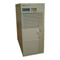
HP 9000 Model D210 Service Manual (472 pages)
Enterprise Servers
Brand:
HP
| Category:
Server
| Size: 4.44 MB
Table of Contents
Table of Contents
4
Installation Summary — D Class
25
Figure 1-1 . Class D Computer Front View (with Door Open)
34
Figure 1-2 . Class D Business Server - Rear View
35
Figure 1-3 . R3X0 Front Panel Controls (Front Bezel Removed)
36
Figure 1-4 . R Class Rear Panel Connectors, Controls, and Indicators
37
Table 1-1 System Features
38
Table 1-3 System Features
39
Remote Management/Access Port Configuration
40
Bit and 32-Bit os Support
40
Soft Power off
40
Table 1-5 64-Bit os Requirements
40
System Model Types
41
Table 1-6 D Class and R Class Models and Model Strings
41
Troubleshooting
81
Calling the Response Center
82
Safety Considerations
83
Hard Failures
83
Power System Troubleshooting
84
Table 3-1 Power-On Troubleshooting
84
Power Supply
85
Power Monitoring
85
LCD Panel Troubleshooting
86
Fan Control
86
Table 3-2 Display Panel Troubleshooting
86
Power Switch Troubleshooting
87
Powertrust UPS Online Error Messages
87
Table 3-3 Power Switch Troubleshooting
87
Troubleshooting System Hardware Faults
88
Table 3-4 Major Code Category Definitions
88
Table 3-5 System Hardware Troubleshooting with Chassis Codes
89
Table 3-6 D200/D210/D310 Memory Troubleshooting
91
Table 3-7 Dx20/Dx30 Memory Troubleshooting
91
Table 3-8 Dx50/Dx60/Dx70/Dx80/R380/D390/R390 Memory Troubleshooting
93
High Priority Machine Check (HPMC)
96
Troubleshooting Hpmcs
96
Table 3-9 HPMC Recovery Procedures
96
D200/Dx10/Dx20/Dx30 Hpmcs
97
Table 3-10 D200/Dx10/Dx20/Dx30 HPMC Codes
97
Dx50/Dx60/Dx70/Dx80/R380/D390/R3Xx Hpmcs
98
Table 3-11 Dx50/Dx60/Dx70/Dx80/D390 HPMC Codes
99
System/Core I/O Card Troubleshooting
105
Figure 3-5 Core I/O Layout Diagram
106
Eisa
107
Figure 3-6 EISA Block Diagram
107
Table 3-12 LAN Troubleshooting Procedure
109
Troubleshooting LAN Problems
109
Table 3-13 System Performance Troubleshooting
110
Soft Errors
110
Diagnostic Tools
111
Operating System Problems
112
Table 3-14 HP-UX System Hang Troubleshooting
112
Performing a HP-UX Automatic Core Dump
113
Avoiding Problems with Automatic Memory Dump
114
Figure 3-7 Using Savecore
114
Table 4-1Major Code Category Definitions
118
Major Code Category 0: - RESERVED
119
Major Code Category 1: Interrupts, Selftests and Diagnostics - CPU/TLB/MIOC
120
Table 4-2 Major Code Category 1: Interrupts
120
Table 4-3 Selftests and Diagnostics - CPU/TLB/MIOC
122
Major Code Category 2: Cache (Selftests and Diagnostics) Codes
124
Table 4-4 Selftests and Diagnostics - ICACHE and DCACHE
124
Major Code Category 3: Processor Dependent Hardware (PDH)
125
Table 4-5 Processor Dependent Hardware (PDH)
125
Major Code Category 4: Selftests and Diagnostics - FP COPROC
127
Table 4-6 Selftests and Diagnostics - FP COPROC
127
Major Code Category 5: Bus Transactions
128
Table 4-7 Bus Transactions
128
Major Code Category 6: RESERVED
129
Major Code Category 7: Selftests and Diagnostics - RAM Cards
130
Table 4-8 Selftests and Diagnostics - RAM Cards
130
Major Code Category 8: I/O Device Faults
131
Table 4-9 I/O Device Faults
131
Major Code Category 9: Console Initialization Errors
133
Table 4-10 Console Initialization Errors
133
Major Code Category A: Boot Device Initialization Errors
134
Table 4-11 Boot Device Initialization Errors
134
Major Code Category B: os PANIC - Output by os
135
Major Code Category C: System Initialization Codes
136
Table 4-12 System Initialization
136
Table 4-13 Boot Device Initialization and IPL Codes for Primary Path
137
Table 4-14 Boot Device Initialization and IPL Codes for All Other Paths
138
Table 4-15 TOC Codes
138
Table 4-16 HPMC Codes
139
Table 4-17 I/O Initialization Codes
139
Table 4-18 EISA Initialization Codes
139
Major Code Category D: SHUTDOWN Codes - Output by the os
140
Major Code Category E: WARNING Codes - Output by the os
141
Major Code Category F: RUN Codes - Output by the os
142
Table 5-1Major Code Category Definitions
144
Major Code Category 0: RESERVED
145
Major Code Category 1: Interrupts, Selftests, Diagnostics, and Boot Codes
146
Table 5-2 Major Code 1, Interrupt
146
Table 5-3 Major Code 1, Selftests and Diagnostics (CPU/TLB)
148
Table 5-4 Major Code 1, Boot Errors (Forward Progress)
150
Table 5-5 Cache (Selftests and Diagnostics) Codes
151
Major Code Category 2: Cache (Selftests and Diagnostics)
151
Table 5-6 Processor Dependent Hardware (PDH) Codes
153
Table 5-7 Late Selftests
155
Major Code Category 4: Late Selftests
155
Major Code Category 5: Bus Transactions
156
Table 5-8 Bus Transactions
156
Major Code Category 6: RESERVED
157
Table 5-9 Memory Subsystem Codes
158
Memory Faults
158
Major Code Category 8: I/O Device Fault Codes
161
Table 5-10 I/O Device Fault Codes
161
Major Code Category 9: Console Initialization Errors
163
Table 5-11 Console Initialization Errors
163
Major Code Category A: Boot Device Initialization Errors
164
Table 5-12 Boot Device Initialization Errors
164
Major Code Category B: Operating System Panic (OS)
165
Table 5-13 HP-UX System Panic Codes
165
Major Code Category C: System Initialization
166
Table 5-14 System Initialization Codes
166
Table 5-15 HP-UX ISL Boot Codes
170
Table 5-16 HP-UX System Initialization Codes
170
Major Code Category D: HP-UX System Shutdown Codes
171
Table 5-17 HP-UX System Shutdown Codes
171
Major Code Category E: WARNING Codes - Output by the os
172
Memory Configuration Rules
173
Table 5-18 HP-UX Run Code
173
Internal Modem Error Codes
175
Table 6-1Major Code Category Definitions
180
Major Code Category 0: RESERVED
181
Major Code Category 1: Selftests, Diagnostics, and Boot Codes
182
Table 6-2 Major Code 1, Selftests and Diagnostics (CPU/TLB)
182
Table 6-3 Major Code 1, Boot Errors (Forward Progress)
183
Major Code Category 2: Cache (Selftests and Diagnostics)
184
Table 6-4 Cache (Selftests and Diagnostics) Codes
184
Table 6-5 Processor Dependent Hardware (PDH) Codes
186
Major Code Category 4: Late Selftests
188
Table 6-6 Late Selftests
188
Major Code Category 5: Bus Transactions
189
Table 6-7 Bus Transactions
189
Major Code Category 6: RESERVED
190
Table 6-8 Memory Subsystem Codes
191
Major Code Category 8: I/O Device Fault Codes
194
Table 6-9 I/O Device Fault Codes
194
Major Code Category 9: Console Initialization Errors
196
Table 6-10 Console Initialization Errors
196
Major Code Category A: Boot Device Initialization Errors
197
Table 6-11 Boot Device Initialization Errors
197
Table 6-12 System Initialization Codes
199
Table 7-1Major Code Category Definitions
208
Major Code Category 0: RESERVED
209
Major Code Category 1: Interrupts, Selftests, Diagnostics, and Boot Codes
210
Major Code Category D: HP-UX System Shutdown Codes
204
Major Code Category E: WARNING Codes - Output by the os
205
Major Code Category F: RUN Codes - Output by the os
206
Major Code Category B: Operating System Panic (OS)
198
Major Code Category C: System Initialization
199
Table 7-2 Major Code 1, Selftests and Diagnostics (CPU/TLB)
210
Major Code Category 2: Cache (Selftests and Diagnostics)
212
Table 7-3 Cache (Selftests and Diagnostics) Codes
212
Table 7-4 Second Level Cache (Selftests and Diagnostics) Codes
212
Table 7-5 Processor Dependent Hardware (PDH) Codes
214
Major Code Category 4: Late Selftests
216
Table 7-6 Late Selftests
216
Major Code Category 5: Bus Transactions
217
Table 7-7 Bus Transactions
217
Major Code Category 6: RESERVED
218
Memory Faults
219
Table 7-8 Memory Subsystem Codes
219
Major Code Category 8: I/O Device Fault Codes
220
Table 7-9 I/O Device Fault Codes
220
Major Code Category 9: Console Initialization Errors
222
Table 7-10 Console Initialization Errors
222
Major Code Category A: Boot Device Initialization Errors
223
Table 7-11 Boot Device Initialization Errors
223
Major Code Category B: Operating System Panic (OS)
224
Major Code Category C: System Initialization
225
Table 7-12 System Initialization Codes
225
Major Code Category D: HP-UX System Shutdown Codes
228
Major Code Category E: WARNING Codes - Output by the os
229
Major Code Category F: RUN Codes - Output by the os
230
Online Diagnostics
232
Using SYSDIAG
233
Offline Utilities
234
HP-UX Support Media
235
Support Media Boot
236
Support Media Main/Utilities Menus
237
Table 9-1 Exchange Assemblies
240
Table 9-2 Non-Exchange Assemblies
241
Web Console
242
Table 9-3 EISA Assemblies
243
Table 9-4 HSC Assemblies
244
Figure 9-1 System Front View (Without Bezel and Side Panel)
245
Figure 9-2 System Front View (with Bezel and Side Panel)
246
Figure 9-3 System Front View (R Class)
247
Figure 9-4 Rear View of I/O Area
248
Prepare the Computer
251
Assemble Tools Required
252
Remove the Front Bezel — D Class
253
Figure 10-1 Hot-Swap Disk Removal/Replacement
253
Figure 10-2 Front Bezel Removal
254
Remove the Front Bezel — R Class
255
Remove the Side Panel (D Class) or Top Panels (R Class)
256
Figure 10-3 Side Panel Removal
256
Figure 10-4 Side Panel Removal
257
Figure 10-5 Side Panel Removal
257
R Class Top Panel Removal
258
Remove the System/Core I/O Board
259
Figure 10-6 Remove EMI Shielding
260
Figure 10-7 Processor/Memory Card Removal
262
Remove the Processor/Memory Card
262
R Class Processor/Memory Card
263
Remove/Replace Memory Modules
265
Figure 10-8 Cache Module Location
266
Remove/Replace Second Level Cache Modules
266
Figure 10-9 Cache Module Key Slots
267
Replace Cache Module
267
Figure 10-10 I/O Card Retainer Bracket Removal - D Class
268
Remove EISA/HSC Cards
268
Figure 10-11 I/O Card Retainer Bracket Removal - R Class
269
Figure 10-12 EISA/HSC Card Removal - D Class
270
Figure 10-13 EISA/HSC Card Removal - R Class
270
Remove All Cables from the System/Core I/O Card
271
Figure 10-14 System/Core I/O Board Replacement
272
Remove the System/Core I/O Board
272
Replace the System/Core I/O Board
273
Replace EISA and HSC Cards
274
Figure 10-15 EMI Shielding Replacement - D Class
275
Figure 10-16 EMI Shielding Replacement - R Class
275
Figure 10-17 IDE Floppy Removal/Replacement
276
Remove and Replace Peripherals
276
Assembling the IDE Floppy Disk
277
Figure 10-18IDE Floppy Disk Assembly Diagram
277
Replace the IDE Floppy
278
Figure 10-19 Removable Media Peripheral Bay Removal/Replacement - D Class
279
Figure 10-20Removable Media Peripheral Bay Removal/Replacement - R Class
280
Figure 10-21 Tape Drive Removal/Replacement
281
Figure 10-22 CD-ROM Drive Removal/Replacement
281
Replace SCSI Removable Media Devices
281
Figure 10-23 D2Xx Disk Assembly Removal/Replacement
282
Remove Single-Ended SCSI Hard Disks
282
Replace Single-Ended SCSI Hard Disks
283
Figure 10-24 Hot Swap Disk Bay
284
Remove the Hot-Swap Bay (D Class Only)
284
Remove and Replace the Hot-Swap Blower (D Class Only)
285
Remove and Replace the Power Supply
286
Figure 10-25 Power Supply Removal/Replacement
287
Remove the Power Supply (R Class)
288
Remove and Replace the Front Fan
289
Figure 10-26 Fan/Display Panel Location
290
Remove and Replace the Rear Fan
291
Remove and Replace the Display Panel
292
Remove and Replace the Power Switch
293
Figure 10-27 Side Panel Replacement
294
Figure 10-28 Side Panel Replacement
295
Figure 10-29 Front Bezel Replacement
296
Peripheral Bays
297
Figure 11-1 D2Xx System
297
Figure 11-2 R3Xx System Peripheral Housing
298
Figure 11-3 D3Xx System
299
Configuration
300
SCSI Cables
301
Table 11-1 50-Pin SCSI Cable
302
Table 11-2 68-Pin SCSI Cable
303
Termination/Term Power
304
Differential
305
Cable and Terminator Part Numbers
306
Table 11-3 50-Pin Low Density
306
Table 11-4 50-Pin Low Density to High Density
307
Table 11-5 50-Pin High Density to High Density
307
Table 11-6 50-Pin Low Density to 68-Pin High Density
307
Table 11-7 50-Pin High Density to 68-Pin High Density
308
Table 11-8 68-Pin High Density to 68-Pin High Density
308
Table 11-9 Terminators
308
Status Returns
309
Internal Peripherals
318
Table 11-12 Mode Specifications
319
Figure 11-4 IDE Floppy Drive
319
HP C2478SZ (C1504B) DDS Tape Drives
320
Figure 11-5 HP C2478SZ Tape Drive
320
Jumpering
321
Figure 11-6 C2478SZ Jumper Diagram
321
Table 11-14 Configuration Switches (for Data Compression DDS-1 Tape Drives)
322
Table 11-15 Configuration Switch 3 (for Media Recognition System)
322
Table 11-16 Recommended Cleaning Frequency
323
Preventative Maintenance
323
Firmware Upgrade Tape Procedure:
324
Figure 11-8 C2478SZ Front Panel
324
Figure 11-9 Cassette and Drive Light Definitions
325
Forced Eject
326
Consequences of a Forced Eject
327
Alternate Method
328
Figure 11-10 Manual Cartridge Removal
328
Diagnostics
329
Figure 11-11 HP A3183A DDS-2 Tape Drive
330
Configuration Switches
331
Figure 11-12 A3183A Jumper Diagram
331
Preventative Maintenance
332
Table 11-18 Configuration Switches (for Data Compression DD-2 Tape Drives)
332
Table 11-19 Configuration Switch 3 (for Media Recognition System)
332
Figure 11-13 A3183A Switch Settings
332
Head Cleaning Procedure
333
Table 11-20 Recommended Cleaning Frequency
333
Firmware Upgrade Failures:
334
Figure 11-14 A3183A Front Panel
334
Forced Eject
335
Figure 11-15 A3183A Indicator Descriptions
335
Triggering a Forced Eject
336
Alternate Method
337
Figure 11-16 Manual Cartridge Removal
337
Exchange Part Number
338
Figure 11-17 HP A3542A DDS-3 Tape Drive
339
Jumpering
340
Figure 11-18 A3542A Jumper Diagram
340
Table 11-22 Configuration Switches (for Data Compression DD-3 Tape Drives)
341
Table 11-23 Configuration Switch 3 (for Media Recognition System)
341
Figure 11-19 A3542A Switch Settings
341
Preventative Maintenance
342
Table 11-24 Recommended Cleaning Frequency
342
Figure 11-20 A3542A Front Panel
343
Firmware Upgrade Tape Procedure:
343
Figure 11-21 A3542AA3542A Indicator Descriptions
344
Forced Eject
345
Manual Cartridge Removal
346
Alternate Method
347
Figure 11-22 Manual Cartridge Removal
347
Diagnostics
348
Figure 11-23 A2944A QIC Tape Drive
349
Figure 11-24 JP1 SCSI Device ID
350
Figure 11-25 Data Cartridge
350
Jumpering
350
Figure 11-26 A2944A Front Panel
351
Preventative Maintenance
351
Figure 11-27 A3184A CD-ROM Drive
352
Figure 11-28 HP A3184A Front Panel
353
Jumpering
354
Figure 11-29 HP A3184A CD-ROM Jumper Diagram
354
Internal Drive Logs
355
Figure 11-30 A3416A CD-ROM Drive
356
Figure 11-31 HP A3184A Front Panel
357
Jumpering
358
Figure 11-32 HP A3416A CD-ROM Jumper Diagram
358
Internal Drive Logs
359
Figure 11-33 A3715A CD-ROM Drive
360
Figure 11-34 HP A3715A Front Panel
361
Jumpering
362
Figure 11-35 HP A3715A CD-ROM Jumper Diagram
362
Internal Drive Logs
363
A3349A 1 Gb Single-Ended SCSI Disk Drive (D200, D210, &D250)
364
Figure 11-36 A3349A Disk Drive
364
Figure 11-37 A3349A Jumpering
365
Table 11-25 J2 Jumper Description
366
Preventative Maintenance
367
Table 11-26
367
A3304A 2 Gb Single-Ended SCSI Disk Drive (D200, D210, &D250)
368
Figure 11-38 A3304A Disk Drive
368
Figure 11-39 A3304A Jumpering
369
Table 11-27 J1 Jumper Function Description
369
Table 11-28 J2 Jumper Functions
370
Table 11-29 J4 Jumper Functions
370
Table 11-13. SCSI ID
371
Table 11-17. SCSI ID
371
Figure 11-40 A3304A Jumpering
371
Figure 11-41 A3304A Jumpering (ST32171N / ST32272N)
372
Figure 11-42 A3304A Jumpering (XP32150L)
372
Table 11-21. SCSI ID
373
Table 11-30. SCSI ID
373
Table 11-31 A3304A J3 Option Jumpers (XP32150L)
373
Figure 11-43 A3304A Jumpering (XP32275)
374
Table 11-32 A3304A J3 Option Jumpers (XP32275L)
374
Preventative Maintenance
375
Figure 11-44 A3660A Disk Drive
376
Figure 11-45 A3660A Jupering (ST34371N / ST345555572N)
377
Table 11-33 4 Gb SE Disks
377
Figure 11-46 A3660A Jumpering (XP34550W)
378
Table 11-34 A3660A J3 Option Jumpers (XP34450W)
378
Preventative Maintenance
379
Specifications
380
Figure 11-47 Hot-Plug Disk Modules
380
Table 11-35 1, 2, 4, and 9 Gb Hot-Plug Disk Drive Modules Specifications
381
Table 11-36. 1, 2, 4, and 9 Gb Hot-Plug Disk Drive Modules Replacement/Exchange
381
Overview
383
Figure 12-1 the Access Port Card
383
Features
384
Figure 12-2 AP Card Bulkhead
384
Figure 12-3 AP Service/Normal Switch
385
Reset
385
Table 12-1 HP at Command Set
386
HP at Commands
386
Table 12-2 S-Register Definitions
392
Table 12-3 Modem Result Codes
393
Enable/Disable Remote Access
394
Enabling or Disabling Remote Access Hardware
395
Figure 12-4 Configure Access Screen
395
Table 12-4 Access Port Commands
396
Table 12-5 AP Card Message and Error Codes
398
Access Port Errors
398
Table A-1 Environmental Specifications
401
Table A-2 AC Electrical Specifications for 350W Power Supply
401
Table A-3 AC Electrical Specifications for 450W Power Supply
402
Figure B-1 Dx50/Dx60 Block Diagram
406
Figure B-2 D200/Dx10 Block Diagram
407
Figure B-3 Dx20/Dx30 Block Diagram
408
Figure B-4 Dx70/Dx80/Rx80 Block Diagram
409
Figure B-5 D390/R390 Block Diagram
410
ISL Commands
411
Dx50/Dx60/Dx70/Dx80/R380/D390/R390 BCH Commands and Screens
412
D200/Dx10/Dx20/Dx30 BCH Commands and Screens
426
BCH Error Messages
438
BCH Warning Messages
440
PDC Update Procedures
444
Current Version Verification
445
Procedure C:
446
Using the Boot Console Handler (BCH)
447
PDC Distribution
448
Downloading the Firmware Patch Via the World Wide Web
449
Configuring the HPESC Account
450
Creating the Firmware Update Tape
451
Firmware Update Procedure
452
Updating from a Tape Created Using Support Media
453
Figure C-1 Hotswap Disk Bay
455
Disk Modules
456
Figure C-2 Disk Module
457
Miscellaneous Signal Description:
457
Figure C-3 Module Chassis CONVERSION
459
Hotswap (Hot-Plug ) Module Chassis Assembly
459
Back Plane for Hotswap Module
460
Figure C-4 Back Plane
460
Figure C-5 Configuration Switch
462
Module Replacement Process
464
Hotswap Example
466
Step
467
Step
468
Step
469
Hot Swap Procedure for Unattached Physical Volumes
470
Advertisement
HP 9000 Model D210 Upgrade Manual (68 pages)
System Memory Upgrade
Brand:
HP
| Category:
Server
| Size: 0.98 MB
Table of Contents
Table of Contents
3
Who Should Use this Guide
6
Overview of Memory Installation
7
Memory Installation Procedure
9
Memory Upgrade Verification
30
Memory Upgrade Verification Procedure
31
Troubleshooting Memory Configuration Error Symptoms
36
Obtaining the Correct Firmware Patch
38
Downloading the Firmware Patch Via the World Wide Web
39
Downloading the Firmware Patch Using FTP
40
R Class System Memory Upgrade
41
Overview of Memory Installation
41
Memory Installation Procedure
43
Memory Upgrade Verification
60
Troubleshooting Memory Configuration Error Symptoms
64
Obtaining the Correct Firmware Patch
65
Downloading the Firmware Patch Via the World Wide Web
66
Downloading the Firmware Patch Using FTP
67
HP 9000 Model D210 Firmware Update Manual (15 pages)
HP Integrity Servers and HP 9000 Servers Firmware Update Options
Brand:
HP
| Category:
Server
| Size: 0.31 MB
Table of Contents
Table of Contents
3
Introduction
4
HP Firmware Manager
4
HP Integrity and HP 9000 Firmware Update Solutions
5
HP Integrity Systems
5
HP Smart Update Manager (HP SUM)
7
Hp Fm
7
Hp Osifm
7
Hp Ofm
8
Additional Firmware Installation Options
8
EFI Image
8
Ilo 3
8
MP-Initiated
8
Firmware Update Options Comparison
8
Firmware Update Options Comparison
9
Frequently Asked Questions
10
How Can I be Notified When New Firmware Packages Are Available
10
Where Can I Download Firmware Packages
10
How Can I View the Firmware Version Installed on My System
11
When Is a Power down and Reboot Required after Updating Firmware
11
Feedback
12
Glossary
13
A Updating Firmware Using Ilo 3
14
Files to Use to Update through Ilo3
14
How to Update Firmware through Ilo 3
14
Advertisement
Advertisement
Related Products
HP D2200sb
HP 9000 Model D200
HP 9000 Model D250
HP 9000 Model D270
HP 9000 Model D280
HP DL100 - ProLiant G2 320GB File Print Appliance
HP ProLiant DL360p
HP ProLiant DL380 Generation9
HP ProLiant DL38
HP ProLiant DL160se - G6 Server
HP Categories
Desktop
Laptop
Server
Monitor
Switch
More HP Manuals
Login
Sign In
OR
Sign in with Facebook
Sign in with Google
Upload manual
Upload from disk
Upload from URL