Sign In
Upload
Manuals
Brands
Lenovo Manuals
Server
ThinkSystem SR650 V3 7D75
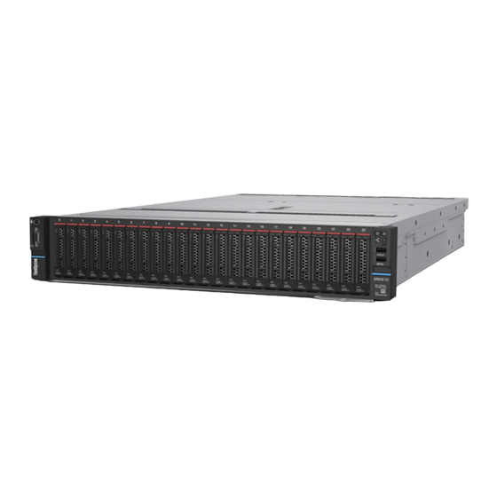
Lenovo ThinkSystem SR650 V3 7D75 Manuals
Manuals and User Guides for Lenovo ThinkSystem SR650 V3 7D75. We have
2
Lenovo ThinkSystem SR650 V3 7D75 manuals available for free PDF download: User Manual, System Configuration Manual
Lenovo ThinkSystem SR650 V3 7D75 User Manual (518 pages)
Brand:
Lenovo
| Category:
Server
| Size: 55.49 MB
Table of Contents
Table of Contents
3
Safety
7
Safety Inspection Checklist
8
Chapter 1. Introduction
11
Features
11
Tech Tips
12
Security Advisories
12
Specifications
13
Technical Specifications
13
Mechanical Specifications
17
Environmental Specifications
18
Management Options
21
Chapter 2. Server Components
25
Front View
25
Front I/O Module
31
Rear View
34
Top View
43
System-Board-Assembly Layout
44
System-Board-Assembly Connectors
45
System-Board-Assembly Switches
46
System Leds and Diagnostics Display
48
Chapter 3. Parts List
49
2.5-Inch Drive Bay Chassis
50
3.5-Inch Drive Bay Chassis
55
Power Cords
59
Chapter 4. Unboxing and Setup
61
Server Package Contents
61
Identify the Server and Access the Lenovo Xclarity
61
Controller
61
Server Setup Checklist
63
Chapter 5. Hardware Replacement Procedures
65
Installation Guidelines
65
Safety Inspection Checklist
66
System Reliability Guidelines
67
Working Inside the Server with the Power on
68
Handling Static-Sensitive Devices
68
Technical Rules
69
Memory Module Installation Rules and Order
69
Pcie Slots and Pcie Adapters
74
Thermal Rules
79
Power on and Power off the Server
82
Power on the Server
83
Power off the Server
83
Server Replacement
83
Remove the Server from Rack
83
Install the Server to Rack
87
Hot-Swap Drive Replacement
92
Remove a Hot-Swap Drive
92
Install a Hot-Swap Drive
93
Air Baffle Replacement
95
Remove the Air Baffle
95
Install the Air Baffle
97
CMOS Battery (CR2032) Replacement
100
Remove the CMOS Battery
100
Install the CMOS Battery
102
Front Drive Backplane Replacement
104
Remove the 2.5-Inch Front Drive Backplane
104
Install the 2.5-Inch Front Drive Backplane
106
Remove the 3.5-Inch Front Drive Backplane
109
Install the 3.5-Inch Front Drive Backplane
111
Front I/O Module Replacement
113
Remove the Front I/O Module
114
Install the Front I/O Module
116
GPU Replacement
118
Remove a GPU Adapter
120
Install a GPU Adapter
123
Heat Sink Torx T30 Nut Replacement
127
Remove a Heat Sink Torx T30 Nut
127
Install a Heat Sink Torx T30 Nut
128
Internal Raid/Hba/Expander Adapter Replacement
129
Remove an Internal Raid/Hba/Expander
130
Adapter
130
Install an Internal Raid/Hba/Expander
131
Adapter
131
Intrusion Switch Replacement
133
Remove the Intrusion Switch
133
Install the Intrusion Switch
134
Drive and M.2 Drive Backplane
136
Replacement
136
Remove an M.2 Drive
137
Install an M.2 Drive
138
Remove the M.2 Backplane
140
Install the M.2 Backplane
143
Memory Module Replacement
146
Remove a Memory Module
146
Install a Memory Module
148
Microsd Card Replacement
149
Remove the Microsd Card
150
Install the Microsd Card
151
Replacement
153
Remove the Middle Drive Cage and Drive
154
Backplanes
154
Install the Middle Drive Backplanes and Drive
156
Cage
156
OCP Module Replacement
159
Remove the OCP Module
159
Install the OCP Module
161
Pcie Adapter and Riser Assembly Replacement
163
Remove a Riser Assembly
165
Remove a Pcie Adapter
169
Install a Pcie Adapter
172
Install a Riser Assembly
176
Power Supply Unit Replacement
179
Safety Precautions
179
Remove a Power Supply Unit
182
Install a Power Supply Unit
184
Processor and Heat Sink Replacement
186
Technician Only)
186
Remove a Processor and Heat Sink
186
Separate the Processor from Carrier and Heat
191
Sink
191
Install a Processor and Heat Sink
193
PSU Air Baffle Replacement
199
Remove a PSU Air Baffle
199
Install a PSU Air Baffle
201
Rack Latches Replacement
202
Remove the Rack Latches
202
Install the Rack Latches
205
RAID Flash Power Module Replacement
207
Chassis
208
Install a RAID Flash Power Module on the Chassis
210
Remove a RAID Flash Power Module from the Air Baffle
212
Install a RAID Flash Power Module on the Air
213
Baffle
213
Remove a RAID Flash Power Module from the Middle 2.5-Inch Drive Cage
214
Install a RAID Flash Power Module on the Middle Drive Cage
216
Rearwall Bracket Replacement
217
Remove a Rearwall Bracket
219
Install a Rearwall Bracket
221
Replacement
223
Remove the 7Mm Drive Cage
223
Remove the 7Mm Drive Backplanes
225
Install the 7Mm Drive Backplanes
227
Install the 7Mm Drive Cage
229
Replacement
231
Drive Cage
231
Cage
233
Drive Cage
235
Cage
236
Drive Cage
238
Cage
240
Remove the 4 X 3.5" Drive Backplane and Drive Cage
242
Install the 4 X 3.5" Drive Backplane and Drive
244
Cage
244
Security Bezel Replacement
247
Remove the Security Bezel
247
Install the Security Bezel
248
System Board Assembly Replacement
250
Technician Only)
250
Remove the Firmware and Rot Security
251
Module
251
Install the Firmware and Rot Security
253
Module
253
Remove the System I/O Board or Processor
257
Board
257
Install the System I/O Board or Processor
260
Board
260
System Fan Replacement
264
Remove a System Fan
265
Install a System Fan
266
System Fan Cage Replacement
269
Remove the System Fan Cage
269
Install the System Fan Cage
270
Serial Port Module Replacement
271
Remove a Serial Port Module
271
Install a Serial Port Module
274
Top Cover Replacement
276
Remove the Top Cover
276
Install the Top Cover
278
Complete the Parts Replacement
279
Chapter 6. Internal Cable Routing
281
Identifying Connectors
281
Drive Backplane Connectors
281
7Mm Drives
286
Front I/O Connectors
289
Gpus
291
M.2 Drive Backplanes
292
RAID Flash Power Module
297
Riser 3 Cage
299
Riser 3/4 Cage
304
Drive Bays
307
One 8 X SAS/SATA Backplane
309
One 8 X Anybay Backplane (Gen 4)
312
One 8 X Nvme Backplane (Gen 4)
316
Two 8 X SAS/SATA Backplanes
317
Two 8 X Anybay Backplanes (Gen 4)
321
Two 8 X Nvme Backplanes (Gen 4)
325
Backplanes
327
Backplanes
333
Backplanes (Gen 4)
339
Three 8 X SAS/SATA Backplanes
343
Three 8 X Anybay Backplanes
392
Three 8 X Nvme Backplanes (Gen 4)
394
Backplanes (Gen 4)
397
Backplanes
399
Backplanes
401
Two 8 X SAS/SATA and One 8 X Anybay
402
Backplanes
402
Backplanes
418
24 X 2.5" SAS/SATA Expander Backplane
421
Drive Bays
426
X 3.5-Inch SAS/SATA Backplane
427
12 X 3.5-Inch SAS/SATA Backplane
429
12 X 3.5-Inch Anybay Backplane
442
Backplane
448
Chapter 7. System Configuration
453
Controller
453
Connection
454
Update the Firmware
455
Configure the Firmware
458
Memory Module Configuration
459
Enable Software Guard Extensions (SGX)
460
RAID Configuration
460
Deploy the Operating System
461
Back up the Server Configuration
462
Chapter 8. Problem Determination
463
Event Logs
463
Display
465
Drive Leds
465
Front Operator Panel Leds
465
Integrated Diagnostics Panel
467
External Diagnostics Handset
472
Rear System Leds
478
XCC System Management Port Leds
479
Power Supply Leds
479
System-Board-Assembly Leds
480
Module
483
General Problem Determination Procedures
484
Resolving Suspected Power Problems
485
Resolving Suspected Ethernet Controller Problems
485
Troubleshooting by Symptom
486
Hard Disk Drive Problems
486
Intermittent Problems
489
Problems
491
Memory Problems
491
Monitor and Video Problems
493
Observable Problems
495
Optional-Device Problems
497
Performance Problems
499
Power on and Power off Problems
500
Power Problems
501
Serial-Device Problems
501
Software Problems
502
Appendix A. Hardware Disassembling for Recycle
503
Recycle
503
Appendix B. Getting Help and Technical Assistance
507
Before You Call
507
Collecting Service Data
508
Contacting Support
509
Appendix C. Documents and Supports
511
Documents Download
511
Support Websites
511
Appendix D. Notices
513
Trademarks
514
Advertisement
Lenovo ThinkSystem SR650 V3 7D75 System Configuration Manual (106 pages)
Brand:
Lenovo
| Category:
Server
| Size: 6.48 MB
Table of Contents
Table of Contents
3
Safety
5
Safety Inspection Checklist
6
Chapter 1. Introduction
9
Features
9
Tech Tips
10
Security Advisories
10
Specifications
11
Technical Specifications
11
Mechanical Specifications
15
Environmental Specifications
17
Management Options
20
Chapter 2. Server Components
25
Front View
25
Front I/O Module
30
Rear View
33
Top View
42
System-Board-Assembly Layout
43
System-Board-Assembly Connectors
44
System-Board-Assembly Switches
45
System Leds and Diagnostics Display
47
Drive Leds
47
Front Operator Panel Leds
48
Integrated Diagnostics Panel
50
External Diagnostics Handset
55
Rear System Leds
61
XCC System Management Port Leds
62
Power Supply Leds
62
System-Board-Assembly Leds
63
Leds on the Firmware and Rot Security
66
Module
66
Chapter 3. Parts List
69
2.5-Inch Drive Bay Chassis
70
3.5-Inch Drive Bay Chassis
75
Power Cords
79
Chapter 4. Unboxing and Setup
81
Server Package Contents
81
Controller
81
Server Setup Checklist
83
Chapter 5. System Configuration
85
Controller
85
Set Front USB Port for Lenovo Xclarity Controller
86
Connection
86
Update the Firmware
87
Configure the Firmware
90
Memory Module Configuration
91
Enable Software Guard Extensions (SGX)
92
RAID Configuration
92
Deploy the Operating System
93
Back up the Server Configuration
94
Appendix A. Getting Help and Technical Assistance
95
Before You Call
95
Collecting Service Data
96
Contacting Support
97
Appendix B. Documents and Supports
99
Documents Download
99
Support Websites
99
Appendix C. Notices
101
Trademarks
102
Important Notes
102
Electronic Emission Notices
102
Taiwan Region BSMI Rohs Declaration
103
Taiwan Region Import and Export Contact Information
103
Advertisement
Related Products
Lenovo ThinkSystem SR650
Lenovo ThinkSystem SR650 7X05
Lenovo ThinkSystem SR650 7X06
Lenovo ThinkSystem SR650 V2
Lenovo ThinkSystem SR655 V3
Lenovo ThinkSystem SR645
Lenovo ThinkSystem SR635
Lenovo ThinkSystem SR670
Lenovo ThinkSystem SR670 V2
Lenovo ThinkSystem SR645 V3
Lenovo Categories
Laptop
Desktop
Server
Monitor
Tablet
More Lenovo Manuals
Login
Sign In
OR
Sign in with Facebook
Sign in with Google
Upload manual
Upload from disk
Upload from URL