Sign In
Upload
Manuals
Brands
Siemens Manuals
Circuit breakers
15-3AFS-500
Siemens 15-3AFS-500 Manuals
Manuals and User Guides for Siemens 15-3AFS-500. We have
1
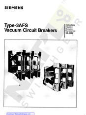
Siemens 15-3AFS-500 manual available for free PDF download: Instructions, Installation, Operation, Maintenance
Siemens 15-3AFS-500 Instructions, Installation, Operation, Maintenance (36 pages)
Vacuum Circuit Breakers
Brand:
Siemens
| Category:
Circuit breakers
| Size: 4.13 MB
Table of Contents
Table of Contents
4
A . Type 3 AFS Vacuum Circuit Breaker Front View
5
AFS Vacuum Circuit Breaker Rear View
6
Figure 2 . Rating Plate
10
Table/Rating Summary & Weights
11
Table
11
Rating Summary & Weights
11
Altitude Correction Factors
11
Closing and Tripping Solenoid Characteristics
12
Table
12
Auxiliary Switch Ratings
12
Typical Innterrupter / Operator Assembly
14
Section through a Typical Vacuum Interrupter
15
Section through a Vaccum Breaker Pole
15
Section through the Typical Vacuum Breaker
15
Afs - 250 4.76 2000
15
Afs - 350 4.76 1200
15
Operating Mechanism Closed Position - Closing Springs Discharged
16
Closing Springs Discharged
17
Figure 10 . Breaker Shaft in Open Position - Closing Springs Discharged
18
Operating Mechanism Open Position - Closing Springs Discharged
18
Figure 11 . Operating Mechanism Section Diagrams : a , B , C . D
19
Figure 12 . Operator Sequential Operation Diagram
21
Figure 13 . Front View of Mechanism Enclosure Arranged for Manual Operation
22
Figure 14 . Typical Elementary Diagram
23
Figure 15 . Construction of Shunt Release
24
Figure 16 a . Latch Detail Shunt Release
24
Figure 16 B . Latch Detail Undervoltage Release
24
Figure 16 C . Undervoltage Blocking Feature
24
Afs - 350 4.76 3000
26
Afs - 500
26
Afs - 500 15.0 2000
26
Afs - 500 8.25 3000
26
Afs - 750
26
Afs - 750 15.0 2000
26
Figure 17 . Operator Lubrication Points
27
Figure 18 . Typical Primary Interrupter Contact Life Curves
28
Figure 19 . Contact Erosion Check
29
Figure 20 a . Lower Pole Support with Insulated Coupler
29
Figure 20 B . Primary Contact Closed - Free Position
30
Figure 20 C . Primary Contact Forced Open by Manual Pressure
30
Figure 21 . Vacuum Tube Replacement Illustration
32
Figure 22 . Illustration Showing Required Technique for Fastening Terminal Clamp Hardware
33
Advertisement
Advertisement
Related Products
Siemens 15-GMI-750
Siemens 15-GMI-1000
Siemens 15-GMl-1000
Siemens 15-GMSG-500
Siemens 15-GMSG-40
Siemens 15-GMSG-50
Siemens 15-GMSG-1000
Siemens 15-GMSG-GCB-40
Siemens 15-GMSG-GCB-50
Siemens 15-GMSG-GCB-63
Siemens Categories
Industrial Equipment
Controller
Control Unit
Oven
Washer
More Siemens Manuals
Login
Sign In
OR
Sign in with Facebook
Sign in with Google
Upload manual
Upload from disk
Upload from URL