Sign In
Upload
Manuals
Brands
Siemens Manuals
Media Converter
6RA7098-4DV62
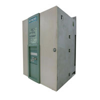
Siemens 6RA7098-4DV62 DC Master Converter Manuals
Manuals and User Guides for Siemens 6RA7098-4DV62 DC Master Converter. We have
1
Siemens 6RA7098-4DV62 DC Master Converter manual available for free PDF download: Operating Instructions Manual
Siemens 6RA7098-4DV62 Operating Instructions Manual (734 pages)
6RA70 Series, Microprocessor-Based Converters from 6kW to 2500kW for Variable-Speed DC Drives, SIMOREG DC Master
Brand:
Siemens
| Category:
Media Converter
| Size: 12.81 MB
Table of Contents
Table of Contents
3
Contents
10
Safety Information
11
Type Spectrum
15
Converter Order Number Code
18
Rating Plate
19
Packaging Label
19
Ordering Information for Options Using Codes
20
Reference to New Products
22
Description
23
Applications
23
Design
23
Special Features of Devices with 460V Rated Connection Voltage
24
Installation of SIMOREG Devices in Cabinets in Accordance with UL508C Standards
24
Mode of Operation
24
Technical Data
25
Load Types
25
Load Cycles for 1Q Applications
26
Load Cycles for 4Q Applications
26
Converters 3AC 400V, 30A to 125A, 1Q
29
Converters 3AC 400V, 210A to 600A, 1Q
30
Converters 3AC 400V, 850A to 2000A, 1Q
31
Converters 3AC 460V, 30A to 125A, 1Q
32
Converters 3AC 460V, 210A to 600A, 1Q
33
Converters 3AC 460V, 850A to 1200A, 1Q
34
Converters 3AC 575V, 60A to 600A, 1Q
35
Converters 3AC 575V, 800A to 2200A, 1Q
36
Converters 3AC 690V, 720A to 2000A, 1Q
37
Converters 3AC 830V, 900A to 1900A, 1Q
38
Converters 3AC 400V, 15A to 125A, 4Q
39
Converters 3AC 400V, 210A to 600A, 4Q
40
Converters 3AC 400V, 850A to 2000A, 4Q
41
Converters 3AC 460V, 30A to 125A, 4Q
42
Converters 3AC 460V, 210A to 600A, 4Q
43
Converters 3AC 460V, 850A to 1200A, 4Q
44
Converters 3AC 575V, 60A to 600A, 4Q
45
Converters 3AC 575V, 850A to 2200A, 4Q
46
Converters 3AC 690V, 760A to 2000A, 4Q
47
Converters 3AC 830V, 950A to 1900A, 4Q
48
Converters 3AC 400V, 3000A, 1Q / 4Q
49
Converters 3AC 575V, 2800A, 1Q / 4Q
50
Converters 3AC 690V, 2600A, 1Q / 4Q
51
Converters 3AC 950V, 2200A, 1Q / 4Q
52
Applicable Standards
54
Certification
55
Abbreviations
55
Shipment, Unpacking
57
Remove the Transportation Protection for Devices with 1500A to 2200A Rated DC
57
Installation
59
Dimension Diagrams for Standard Devices
61
Converters: 3AC 400V and 460V, 30A, 1Q
61
Converters: 3AC 400V and 575V, 60A to 280A, 1Q
62
Converters: 3AC 400V and 575V, 400A, 1Q
63
Converters: 3AC 400V and 575V, 600A, 1Q
64
Converters: 3AC 400V, 575V and 690V, 720A to 850A, 1Q
65
Converters: 3AC 400V,460V, 575V, 690V and 830V, 900A to 1200A, 1Q
66
Converters: 3AC 400V, 575V, 690V, and 830V, 1500A to 2000A, 575V/2200A 1Q
67
Converters: 3AC 400V / 3000A, 3AC 575V / 2800A, 3AC 690V / 2600A, 3AC 950V / 2200A 1Q
68
Converters: 3AC 400V and 460V, 15A to 30A, 4Q
69
Converters: 3AC 400V and 575V, 60A to 280A, 4Q
70
Converters: 3AC 400V and 575V, 400A to 600A, 4Q
71
Converters: 3AC 400V, 575V and 690V, 760A to 850A, 4Q
72
Converters: 3AC 400V, 460V, 575V, 690V and 830V, 950A to 1200A, 4Q
73
Converters: 3AC 400V, 575V, 690V, and 830V, 1500A to 2000A, 575V/2200A 4Q
74
Converters: 3AC 400V / 3000A, 3AC 575V / 2800A, 3AC 690V / 2600A
75
3Ac 950V / 2200A 4Q
75
Dimension Diagrams of the Devices with Additional Cable Connections on the Top of the Device
76
Converters: 3AC 460V, 60A to 125A, 1Q
76
Converters: 3AC 460V, 210A to 280A, 1Q
77
Converters: 3AC 460V, 450A to 600A, 1Q
78
Converters: 3AC 460V, 850A, 1Q
79
Converters: 3AC 460V, 60A to 125A, 4Q
80
Converters: 3AC 460V, 210A to 280A, 4Q
81
Converters: 3AC 460V, 450A to 600A, 4Q
82
Converters: 3AC 460V, 850A, 4Q
83
Mounting Options
84
Terminal Expansion Board CUD2
84
Optional Supplementary Boards
85
Local Bus Adapter (LBA) for Mounting Optional Supplementary Boards
85
Mounting of Optional Supplementary Boards
85
Connections
87
Installation Instructions for Proper EMC Installation of Drives
88
Fundamental Principles of EMC
88
What Is EMC
88
Noise Radiation and Noise Immunity
88
Limit Values
88
SIMOREG Converters in Industrial Applications
89
Non-Grounded Supply Systems
89
EMC Planning
89
Proper EMC Installation of Drives (Installation Instructions)
90
General
90
Rules for Proper EMC Installation
90
Information on Line-Side Harmonics Generated by Converters in a
101
Block Diagrams with Recommended Connection
103
Converters: 15A to 125A
103
Converters: 210A to 280A
104
Converters: 400A to 3000A with a 3-Phase Fan
105
Converters: 450A to 850A with a 1-Phase Fan
106
Parallel Connection of Converters
107
Circuit Diagram Showing Parallel Connection of SIMOREG Converters
107
Parameterization of SIMOREG Converters for Parallel Connection
108
Standard Operating Mode
108
Operating Mode "N+1 Mode" (Redundancy Mode of the Armature Supply)
109
Redundancy Mode of the Field Supply
111
Power Connections
112
Converters: 30A, 1Q
112
Converters: 60A, 1Q
113
Converters: 90A to 280A, 1Q
114
Converters: 400A to 600A, 1Q
115
Converters: 720A, 1Q
116
Converters: 800 to 850A, 1Q
117
Converters: 900A to 950A, 1Q
118
Converters: 1000 to 1200A, 1Q
119
Converters: 1500 to 2000A, 575V/2200A, 1Q
120
Converters: 400V/3000A, 575V/2800A, 690V/2600A, 950V/2200A 1Q
122
Converters: 15 to 30A, 4Q
124
Converters: 60A, 4Q
125
Converters: 90A to 210A, 4Q
126
Converters: 280A, 4Q
127
Converters: 400A, 4Q
128
Converters: 450A to 600A, 4Q
129
Converters: 760A, 4Q
130
Converters: 850A, 4Q
131
Converters: 950A to 1000A, 4Q
132
Converters: 1100 to 1200A, 4Q
133
Converters: 1500 to 2000A, 575V/2200A, 4Q
134
Converters: 400V/3000A, 575V/2800A, 690V/2600A, 950V/2200A 4Q
136
Field Supply
138
Fuses
141
Recommended Fuses for Field Circuit
141
Fuses for Armature Circuit
141
Converters 1Q: 400V, 575V, 690V, 830V and 950V
141
Fuses and Commutating Reactors
141
Converters 1Q: 460V
142
Converters 4Q: 400V, 575V, 690V, 830V and 950V
143
Converters 4Q: 460V
144
F1 and F2 Fuses in the Power Interface
144
Terminal Arrangement
145
Terminal Assignments
148
Start-Up
159
General Safety Information
159
Operator Control Panels
161
Simple Operator Control Panel (PMU)
161
User-Friendly Operator Control Panel (OP1S)
162
Parameterization Procedure
164
Parameter Types
164
Reset to Default Value and Adjust Offset
166
Start-Up Procedure
167
Manual Optimization (if Necessary)
175
Manual Setting of Armature Resistance R a (P110) and Armature Inductance L a (P111)
176
Starting up Optional Supplementary Boards
178
Procedure for Starting up Technology Boards (T100, T300, T400)
178
Sequence of Operations for Starting up PROFIBUS Boards (CBP2)
180
Mechanisms for Processing Parameters Via the PROFIBUS
182
Diagnostic Tools
183
Sequence of Operations for Starting up CAN Bus Boards (CBC)
187
Description of CBC with CAN Layer 2
188
Description of CBC with Canopen
192
Introduction to Canopen
192
Functionality of CBC with Canopen
193
Requirements for Operating the CBC with Canopen
194
Procedure for Starting up the Pulse Encoder Board (SBP)
203
Sequence of Operations for Starting up Devicenet Boards (CBD)
204
Sequence of Operations for Starting up the Serial I/O Board (SCB1)
212
Diagnostic Tools
214
Structure of Request/Response Telegrams
215
Transmission of Double-Word Connectors for Technology and Communication Modules
218
General Explanations of Terms and Functionality
357
Computation Cycles, Time Delay
362
Switch-On, Shutdown, Enabling
363
Switch-On / Shutdown (on / OFF) Terminal 37 - Control Word 1, Bit 0
364
Operating Enable (Enable) Terminal 38 - Control Word 1, Bit 3
367
Definitions
368
Control Signals for Ramp-Function Generator
369
Ramp-Up Integrator
370
Limitation after Ramp-Function Generator
371
Crawling
372
Safety Shutdown (E-Stop)
373
Activation Command for Holding or Operating Brake (Low Active)
374
Switch on Auxiliaries
377
Speed Controller
378
Serial Interfaces
379
Serial Interfaces with Peer-To-Peer Protocol
383
Dynamic Overload Capability of Power Section
390
Configuring for Dynamic Overload Capability
391
Characteristics for Determining the Dynamic Overload Capability for Intermittent Overload Operation
393
Speed-Dependent Current Limitation
428
Setting the Speed-Dependent Current Limitation for Motors with Commutation Transition
429
Setting of Speed-Dependent Current Limitation for Motors Without Commutation Transition
430
Automatic Restart
431
Direction of Rotation Reversal Using Field Reversal
432
Braking with Field Reversal
433
Status Description of some Bits of Status Word ZSW1
435
Pulse Series Connection
436
Faults and Alarms
437
Fault Messages
438
Alarms
461
Analog Outputs
543
Connector List
649
Binector List
675
Replacement of Components
713
Replacement of Pcbs
717
Replacement of Fuses and Thyristor Assemblies on Converters of 1500A and above
719
Technical Support
721
Spare Parts
722
Scope of Delivery
723
Setting up an Online Link to the SIMOREG
724
Advertisement
Advertisement
Related Products
Siemens 6RA7095-4KS22
Siemens 6RA7097-4KS22
Siemens 6RA7095-4DV62
Siemens 6RA7091-6FV62
Siemens 6RA7095-4GV62
Siemens 6RA7093-4GV62
Siemens 6RA7090-6GV62
Siemens 6RA7096-4GV62
Siemens 6RA7095-4KV62
Siemens 6RA7096-4MV62
Siemens Categories
Industrial Equipment
Controller
Control Unit
Oven
Washer
More Siemens Manuals
Login
Sign In
OR
Sign in with Facebook
Sign in with Google
Upload manual
Upload from disk
Upload from URL