Sign In
Upload
Manuals
Brands
Siemens Manuals
Measuring Instruments
ARDOCELL PA 40 AF 2/C
Siemens ARDOCELL PA 40 AF 2/C Manuals
Manuals and User Guides for Siemens ARDOCELL PA 40 AF 2/C. We have
1
Siemens ARDOCELL PA 40 AF 2/C manual available for free PDF download: Operating Manual
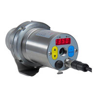
Siemens ARDOCELL PA 40 AF 2/C Operating Manual (132 pages)
Digital Two-Colour Pyrometer
Brand:
Siemens
| Category:
Measuring Instruments
| Size: 2.86 MB
Table of Contents
Table of Contents
5
Product Numbers ARDOCELL PA
9
Miscellaneous
14
Information about this Manual
14
Explanation of Symbols
14
Liability and Warranty
14
Copyright
15
Safety
15
Intended Use
15
User's Responsibility
16
Safety Requirements
16
Electromagnetic Compatibility
16
General Description
16
Operating Controls and Display
17
Quick Reference Guide
18
PA Connector Pin Assignment
18
Power Requirement 24 V DC
19
Current Outputs 0/4 - 20Ma
19
Switching Output
20
Getting Started
21
General Installation Tips
21
Pyrometer Alignment to Target
21
Pyrometers with Laser Sighting
22
Safety Instructions and Precautions
23
Pyrometer with Camera
24
Setting Parameters at the Pyrometer (Basic Configuration)
24
Setting Emissivity (Spectral Mode)
25
Setting the Emissivity Ratio (Two-Colour/Ratio Mode)
26
Adjusting the Soot Factor (Flame Temperature Measurement)
26
Output Current Range
27
Simulated Current Signal for Functional Testing
27
How the Pyrometer Functions
28
Internal Signal Processing
28
Configuration and Setup
29
Signal Conditioning
29
I/O Configuration
37
Digital Inputs
42
General Functions (Configuration Layer C011)
43
Simulate Current Signals for Analogue Output Ao1 and Ao2
44
(Configuration Layer: C 100)
44
Setting Parameters at the Device
45
Configuration Level
45
Cellaview Software
52
Installation of the USB Driver
53
How to Operate the Pyrometer with the Cellaview Software
54
Cellaview Via USB Point-To-Point Connection
54
Cellaview Via RS485 Point-To-Point Connection
54
Cellaview Via RS485 Bus Connection
56
Termination of RS485 Bus
58
Operation of the Pyrometer Via Terminal Program
58
Serial Data Transmission of Temperature Data
59
Terminal Connection Via USB
60
Terminal Connection Via RS485
61
User-Defined Calibration / Scaling of the Current Output
63
Calibration/Scaling Via Cellaview
64
Calibration/Scaling Via Terminal Connection
64
Shielding and Grounding
66
Potential Equalisation
66
Connectivity Examples
68
Connection to VK 02/A Cable
68
Connection to da 230 Digital Display Unit
68
Theory of Non-Contact Temperature Measurements
69
Advantages of Non-Contact Temperature Measurement
69
Measurements at Black Bodies (Cavity Radiators)
69
Measurements of Real Radiators
70
Emissivity Coefficient Table PA (Spectral Mode)
71
Maintenance
72
Cleaning the Pyrometer Lens
72
Technical Data PA 40 AF 20
73
Field of View Diagram PA 40 AF 20
74
Technical Data PA 40 (650 - 1700 °C)
75
Field of View Diagrams PA 40
76
Technical Data PA 40 (750 - 2400 °C)
78
Field of View Diagrams PA 40 (750 - 2400 °C)
79
Technical Data PA 40 (850 -3000 °C)
81
Field of View Diagrams PA 40 (850 -3000 °C)
82
Technical Data PA 43 AF 20 (MR 500 -1400 °C)
85
Field of View Diagram PA 43 AF 20
86
Technical Data PA 43 (MR 650 - 1700 °C)
87
Field of View Diagrams (MR 650 - 1700 °C)
88
Technical Data PA 43 (MR 750 - 3000 °C)
94
Field of View Diagrams PA 43 (MR 750 - 3000 °C)
95
Technical Data PA 43 AF 17
101
Field of View Diagram PA 43 AF 17
102
Technical Data PA 47
103
Field of View Diagrams PA 47
104
Technical Data PA 50
105
Field of View Diagrams PA 50
106
Technical Data PA 60
108
Field of View Diagram PA 60
109
Dimensions
110
Technical Data Camera
111
Accessories
113
Mounting Angle PA 11/K
113
Polarising Filter
114
Mounting Bracket PA 11/U
115
Quarz-Window PA 20/I
116
Cable VK 02/A
117
Cable VK 02/F
118
Mounting Combinations
119
Mounting Combination PA 20-007
119
Mounting Combination PA 20-010
120
Glossary
121
Shipping, Packaging and Disposal
122
Inspecting Your Shipment
122
Packaging
122
Disposal of Used Apparatus
122
Copyright
123
Default Settings
124
Temperature Measurement Using Two-Colour/Ratio Mode (Configuration Layer: C001)
124
Temperature Measurement Using Spectral Mode (Configuration Layer: C002, C003)
125
Configuration I/O (Configuration Layer: C010)
126
General Functions (Configuration Layer: C011)
127
Advertisement
Advertisement
Related Products
Siemens ARDOCELL PA 40 AF 20/L
Siemens ARDOCELL PA 40 AF 20/C
Siemens ARDOCELL PA 40 AF 2/L
Siemens ARDOCELL PA 40 AF 21/L
Siemens ARDOCELL PA 40 AF 21/C
Siemens ARDOCELL PA 40 AF 22/L
Siemens ARDOCELL PA 40 AF 22/C
Siemens ARDOCELL PA 40 AF 23/L
Siemens ARDOCELL PA 40 AF 23/C
Siemens ARDOCELL PA 40 AF 1/L
Siemens Categories
Industrial Equipment
Controller
Control Unit
Oven
Washer
More Siemens Manuals
Login
Sign In
OR
Sign in with Facebook
Sign in with Google
Upload manual
Upload from disk
Upload from URL