Sign In
Upload
Manuals
Brands
Siemens Manuals
Measuring Instruments
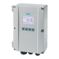
FST020 IP65 NEMA 4X
Siemens FST020 IP65 NEMA 4X Manuals
Manuals and User Guides for Siemens FST020 IP65 NEMA 4X. We have
2
Siemens FST020 IP65 NEMA 4X manuals available for free PDF download: Operating Instructions Manual
Siemens FST020 IP65 NEMA 4X Operating Instructions Manual (190 pages)
Ultrasonic Flowmeters
Brand:
Siemens
| Category:
Measuring Instruments
| Size: 2.96 MB
Table of Contents
Table of Contents
3
1 Introduction
9
Purpose of this Documentation
9
Product Compatibility
9
Document History
9
Connecting
9
Device Documentation Package
10
Items Supplied
10
Checking the Consignment
11
Further Information
11
Notes on Warranty
12
2 Safety Notes
13
Precondition for Use
13
Warning Symbols on the Device
13
Laws and Directives
13
Conformity with European Directives
14
Lithium Batteries
14
3 Description
15
Overview
15
Design
15
Features
16
4 Installing/Mounting
19
Chapter Overview (Transmitter)
19
Installation Location Requirements
19
Environment
19
Normal Environmental Conditions
20
Installation Instructions
20
Wall Mount Transmitter
20
5 Connecting
25
Basic Safety Notes
25
Missing Pe/Ground Connection
25
Energized Devices
25
Disconnecting Device
26
Device Nameplates
26
Device Nameplate
27
Transmitter Power Supply, Communications and I/O Connections
28
Sensor Connections
28
Connecting the Power Supply
28
Connecting Inputs/Outputs
30
Connection Wiring
31
Finishing the Transmitter Connection (Wall Mount Housing)
33
6 Commissioning
35
Basic Safety Notes
35
Hazardous Contact Voltage
35
General Requirements
36
Power-Up
36
Local Display
36
Initial Startup
36
Commissioning Via Local Display
37
Chapter Overview
37
Wizards
38
Quick Commissioning Wizard (Menu Item 1.1)
38
Quick Commissioning Wizard (Wizard)
38
Sensor Settings Wizard (Menu Item 1.2)
38
Sensor Settings Wizard (Wizard)
39
Process Values Wizard (Menu Item 1.3)
43
Process Values Wizard (Wizard)
44
Inputs/Outputs Wizard
45
Navigating the Menu Structure
45
Chapter Overview
45
Navigation View
45
Navigating the Menu Structure
46
7 Operating
47
Display Views
47
Access Control
47
Operating the FST020
48
Fixed Display Texts
48
Reading the Process Values
49
Operating the Totalizer
51
Handling Alarms
52
Reading the Diagnostic Values
53
Reading / Changing Parameters
53
Parameter View Introduction
53
Alphanumeric Parameters
53
Changing the Resolution
55
8 Service and Maintenance
57
Basic Safety Notes
57
Impermissible Repair of the Device
57
Recalibration
57
Maintenance and Repair Work
57
Maintenance
57
Service and Maintenance Information
58
Return Procedure
59
Disposal
59
9 Diagnosing and Troubleshooting
61
Introduction
61
Device Status Icons
61
Fault Codes and Corrective Actions
62
Alarm Messages
62
10 Technical Data
65
Power
65
Inputs
65
Outputs
66
Construction
66
Operating Conditions
67
Approvals
68
Sensorflash
68
11 Dimension Drawings
69
Dimension Drawing
69
12 Replacement Parts
71
AC Transmitter Exploded View
71
Modbus Communication
73
Modbus Addressing Model
73
Coil Configuration
75
A.3 Coil Configuration
75
Modbus Register Mapping
76
Integer Byte Order
78
Float Byte Order
78
Modbus Function Codes
78
Access Control
80
Modbus Holding Register Tables
80
Modbus Holding Registers Tables
80
A.8 Access Control
80
Process Values
81
A.9.2 Process Values
81
Totalizers
82
A.9.3 Totalizers
82
Units
84
A.9.4 Units
84
Device Reset
89
A.9.5 Device Reset
89
Setup
90
Sensor
90
A.9.6 Setup
90
Process Values
108
A.9.6.2 Process Values
108
Totalizers
112
A.9.6.3 Totalizers
112
Inputs and Outputs
113
Date and Time
126
Local Display
127
A.9.6.6 Local Display
127
Selectable Values Dependent on the View Type
137
Process Value Filter Masks
138
Maintenance and Diagnostics
139
Identification
139
Diagnostic Events
141
Active Events
141
A.9.8 Diagnostic Events
141
Diagnostic Log
145
A.9.8.2 Diagnostic Log
145
Alarm Items
146
Diagnostics
150
Sensor
150
A.9.9 Diagnostics
150
Dsl
151
A.9.9.2 Dsl
151
Temperature Monitoring
152
A.9.9.3 Temperature Monitoring
152
Inputs and Outputs
153
Peak Values
155
A.9.9.5 Peak Values
155
Characteristics
159
Transmitter
159
Sensor Frontend
159
A.9.10 Characteristics
159
Sensorflash
160
A.9.11 Sensorflash
160
Data Logging
161
A.9.11.2 Data Logging
161
Simulation
162
Inputs and Outputs
162
A.9.12 Simulation
162
Process Values
164
A.9.12.2 Process Values
164
Alarms
165
A.9.12.3 Alarms
165
Audit Trail
167
Operating Time
167
Parameter Change Log
167
A.9.13 Audit Trail
167
FW Update Change Log
169
Communication
170
Service Channel
170
Security
170
Access Management
170
A.9.14 Communication
170
Certificates and Support
173
Certificates
173
Technical Support
173
B.1 Certificates
173
QR Code Label
174
B.3 QR Code Label
174
Simatic Pdm
175
Commissioning with PDM
175
Introduction
175
Functions in SIMATIC PDM
175
Supported SIMATIC PDM Versions
175
Initial Setup
176
Integrating the EDD
176
C.1.4 Initial Setup
176
Adding Device to Communication Network
178
Configuring a New Device
179
Wizard - Quick Start Via PDM
180
Wizard - Clamp-On Configuration
181
Wizard - Zero Point Adjustment
181
Changing Parameter Settings Using SIMATIC PDM
182
Parameters Accessed Via Drop-Down Menus
183
Process Variables
184
C.1.13 Process Variables
184
Index
187
Advertisement
Siemens FST020 IP65 NEMA 4X Operating Instructions Manual (118 pages)
Ultrasonic flowmeters
Brand:
Siemens
| Category:
Measuring Instruments
| Size: 4.16 MB
Table of Contents
Table of Contents
3
Introduction
7
Purpose of this Documentation
7
Product Compatibility
7
Document History
7
Device Documentation Package
8
Items Supplied
8
Checking the Consignment
9
Security Information
9
Transportation and Storage
10
Further Information
10
Notes on Warranty
11
Safety Notes
13
Precondition for Use
13
Warning Symbols on the Device
13
Laws and Directives
13
Conformity with European Directives
14
Lithium Batteries
14
Description
15
Overview
15
Design
15
Features
16
Installing/Mounting
19
Chapter Overview (Transmitter)
19
Installation Location Requirements
19
Environment
19
Normal Environmental Conditions
20
Installation Instructions
20
Wall Mount Transmitter
20
Connecting
25
Basic Safety Notes
25
Missing Pe/Ground Connection
25
Energized Devices
25
Disconnecting Device
26
Device Nameplates
26
Device Nameplate
27
Transmitter Power Supply, Communications and I/O Connections
28
Sensor Connections
28
Connecting the Power Supply
28
Connecting Inputs/Outputs
30
Connection Wiring
31
Finishing the Transmitter Connection (Wall Mount Housing)
33
Commissioning
35
Basic Safety Notes
35
Hazardous Contact Voltage
35
General Requirements
36
Power-Up
36
Local Display
36
Initial Startup
36
Commissioning Via Local Display
37
Chapter Overview
37
Wizards
37
Quick Commissioning Wizard (Menu Item 1.1)
37
Quick Commissioning Wizard (Wizard)
38
Sensor Settings Wizard (Menu Item 1.2)
38
Sensor Settings Wizard (Wizard)
39
Process Values Wizard (Menu Item 1.3)
43
Process Values Wizard (Wizard)
44
Inputs/Outputs Wizard
45
Navigating the Menu Structure
45
Chapter Overview
45
Navigation View
45
Navigating the Menu Structure
46
Operating
47
Display Views
47
Access Control
47
Operating the FST020
48
Fixed Display Texts
48
Reading the Process Values
49
Operating the Totalizer
51
Handling Alarms
51
Reading the Diagnostic Values
53
Reading / Changing Parameters
53
Parameter View Introduction
53
Alphanumeric Parameters
53
Changing the Resolution
54
Parameter Assignment
57
Multipoint Calibration
57
Inputs and Outputs
59
Digital Input
67
Service and Maintenance
69
Basic Safety Notes
69
Impermissible Repair of the Device
69
Recalibration
69
Maintenance and Repair Work
69
Maintenance
69
Service and Maintenance Information
70
Return Procedure
71
Disposal
71
Diagnostics and Troubleshooting
73
Introduction
73
Device Status Icons
73
Fault Codes and Corrective Actions
74
Alarm Messages
74
Technical Specifications
77
Power
77
Inputs
77
Outputs
78
Construction
78
Operating Conditions
79
Approvals
80
Sensorflash
80
Dimension Drawings
81
Dimension Drawing
81
Replacement Parts
83
AC Transmitter Exploded View
83
Modbus Communication
85
Modbus Addressing Model
85
Modbus Function Codes
85
Changing Modbus Communication Settings
90
Modbus Communication
91
Coil Configuration
92
Modbus Register Mapping
93
Integer Byte Order
95
Float Byte Order
95
Modbus Function Codes
96
Access Control
97
Product Documentation and Support
99
Product Documentation
99
Technical Support
100
Simatic Pdm
101
Commissioning with SIMATIC PDM
101
Overview SIMATIC PDM
101
Check SIMATIC PDM Version
101
Deactivate Buffers When Connecting Via Serial Modem
102
Updating the Electronic Device Description (EDD) or Field Device Integration (FDI)
103
Adding Device to Communication Network
104
Integrating a HART Device in a HART Modem Network
105
Configuring a New Device
108
Wizard - Quick Start Via PDM
108
Wizard - Clamp-On Configuration
110
Zero Point Adjustment
110
Changing Parameter Settings Using SIMATIC PDM
111
SIMATIC PDM Structure View Image
112
Parameters Accessed Via PDM Menus
112
Process Variables
114
HMI Menu Structure
115
Index
117
Advertisement
Related Products
Siemens FST020
Siemens SITRANS FST030
Siemens SITRANS FS230
Siemens FS20
Siemens SITRANS FST090
Siemens SITRANS FS130
Siemens SITRANS FSS100
Siemens Sitrans FUG1010
Siemens FIDAMAT 6
Siemens FT2001-A1
Siemens Categories
Industrial Equipment
Controller
Control Unit
Oven
Washer
More Siemens Manuals
Login
Sign In
OR
Sign in with Facebook
Sign in with Google
Upload manual
Upload from disk
Upload from URL