Sign In
Upload
Manuals
Brands
Siemens Manuals
Control Systems
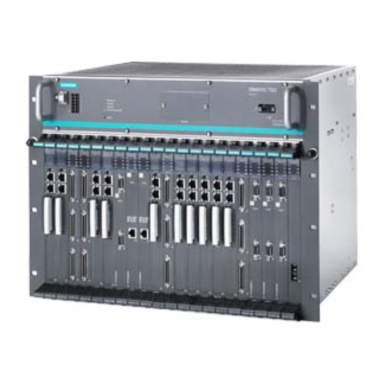
SIMATIC TDC
Siemens SIMATIC TDC Manuals
Manuals and User Guides for Siemens SIMATIC TDC. We have
2
Siemens SIMATIC TDC manuals available for free PDF download: System Manual
Siemens SIMATIC TDC System Manual (228 pages)
Brand:
Siemens
| Category:
Control Systems
| Size: 3.44 MB
Table of Contents
Preface
3
Table of Contents
7
1 Installation and EMC Guidelines
13
Qualified Personnel
13
Danger and Warning Information
14
Introduction
15
CE Label
16
EMC Directive
16
Low-Voltage Directive
17
Machinery Directive
17
Installation
17
Fire Protection
18
Control Cabinet
20
Equipotential Bonding
22
Protective Ground
28
Power Losses in the Control Cabinet
29
Power Supply
30
Rack
32
Cables
32
ESD Directives
35
2 General Technical Specifications
37
Climatic Conditions
37
Electrical Protection and Safety Requirements
37
External Supply of the SIMATIC TDC Modules (Digital Outputs)
37
Mechanical Requirements
38
Electromagnetic Requirements (Industry)
38
3 Rack
39
Rack UR6021 (6DD1682-0CH3)
39
Areas of Application
39
Mechanical Layout
40
Control and Display Elements
41
Status and Fault Displays
42
Power Supply
42
Wiring Diagram
43
Voltage Monitoring
44
Battery Backup
45
Modules
47
Power Supply Potentials
47
Ventilation/Cooling
48
Technical Specifications
51
Rack UR5213 (6DD1682-0CH2)
54
Areas of Application
54
Mechanical Layout
54
Control and Display Elements
55
Status and Fault Displays
56
Power Supply
56
Wiring Diagram
57
Voltage Monitoring
58
Battery Backup
59
Modules
60
Power Supply Potentials
60
Ventilation/Cooling
61
Technical Specifications
63
Rack UR5213 (6DD1682-0CH0)
66
Areas of Application
66
Mechanical Layout
66
Control and Display Elements
67
Status and Fault Displays
68
Power Supply
68
Voltage Monitoring
70
Battery Backup
71
Ventilation/Cooling
72
Technical Specifications
73
Slot Covers
74
4 CPU Modules
75
CPU Module CPU555
75
Areas of Application
75
Control and Display Elements
76
Status and Fault Displays
78
Application Notes and Immunity to Interference
81
Connection Options
82
Additional Components
82
Pin Assignments
83
Note on Firmware Update
83
Technical Specifications/Performance Features
84
CPU Module CPU550/CPU551
88
Areas of Application
88
Using the CPU551 - 6DD1600-0BA3
88
Control and Display Elements
90
Status and Fault Displays
91
Application Notes and Immunity to Interference
94
Connection Options
94
Additional Components
95
Pin Assignments
95
Technical Specifications/Performance Features
97
5 Signal Modules
103
SM500 Signal Module
103
Areas of Application
103
Control and Display Elements
103
Status and Fault Displays
105
Application Notes and Immunity to Interference
105
Connection Options
106
Additional Components
107
Incremental Encoder Input Settings
108
Pin Assignments
110
Technical Specifications/Performance Features
116
6 Communication Modules
121
CP50M1 Communication Module
121
Areas of Application
121
Control and Display Elements
123
Status and Fault Displays
124
Application Notes and Immunity to Interference
125
Connection Options
125
Additional Components
126
Pin Assignments
127
Technical Specifications/Performance Features
128
CP51M1 Communication Module
130
Areas of Application
130
Control and Display Elements
131
Status and Fault Displays
132
Application Notes and Immunity to Interference
133
Connection Options
133
Additional Components
134
Pin Assignments
134
Technical Specifications/Performance Features
135
GDM Memory Module CP52M0
137
Areas of Application
137
Control and Display Elements
138
Status and Fault Displays
139
Application Notes and Immunity to Interference
141
Connection Options
144
Additional Components
144
Pin Assignments
145
Technical Specifications/Performance Features
147
CP52IO GDM Interface Module
149
Areas of Application
149
Control and Display Elements
150
Status and Fault Displays
152
Application Notes and Immunity to Interference
152
Connection Options
153
Additional Components
154
Pin Assignments
154
Technical Specifications/Performance Features
155
CP52A0 GDM Access Module
156
Areas of Application
156
Using the CP52A0 - 6DD1660-0BH1
157
Control and Display Elements
157
Status and Fault Displays
159
Application Notes and Immunity to Interference
160
Connection Options
161
Additional Components
161
Pin Assignments
162
Technical Specifications/Performance Features
162
CP53M0 Coupling Module
163
Areas of Application
163
CP53M0 as Slave
163
CP53M0 as Master
165
Control and Display Elements
167
Status and Fault Displays
169
Application Notes and Immunity to Interference
171
Connection Options
172
Additional Components
172
Pin Assignments
173
Technical Specifications/Performance Features
173
7 Interface Module
175
Interface Module SB10
175
Signals
177
Application Notes
178
Technical Specifications
179
Pin Assignment
180
Block Diagram
181
Interface Module SB60
182
Signals
184
Application Notes
184
Technical Specifications
185
Pin Assignment
186
Block Diagram
187
Interface Module SB61
188
Signals
190
Application Notes
191
Technical Specifications
194
Pin Assignment
195
Block Diagram
196
Interface Module SB70
197
Signals
199
Application Notes
200
Technical Specifications
201
Pin Assignment
202
Block Diagram
203
Interface Module SB71
204
Signals
206
Application Notes
206
Technical Specifications
208
Pin Assignment
209
Block Diagram
210
Interface Modules SU12 und SU13
211
Function Description
212
Additional Components
213
Application Notes
213
Pin/Terminal Assignment X1/X2
214
Technical Specifications
216
8 Submodules
217
Program Memory Modules CPU555
217
Program Memory Modules CPU550/551
219
Service & Support
221
A.1 Service & Support
221
Index
225
Advertisement
Siemens SIMATIC TDC System Manual (200 pages)
Hardware
Brand:
Siemens
| Category:
Control Unit
| Size: 3.25 MB
Table of Contents
Preface
3
Table of Contents
7
1 General Technical Specifications
13
Installation and EMC Guidelines
13
Definitions
13
Qualified Personnel
13
Danger and Warning Notes
14
Introduction
14
CE Label
15
EMC Directive
15
Low-Voltage Directive
16
Machinery Directive
16
Overview
16
SIMATIC TDC Outputs
16
Expert Personnel
16
Input of External Voltages
16
Installation
17
Repairs/Maintenance
17
Supplier
17
Address
17
Fire Protection
18
Control Cabinet
20
Arrangement and Clearances
20
Equipotential Bonding
21
General
21
Principle of Component Connections
21
Equipotential Busbar
22
Practical Application Examples
23
Protective Ground
27
Power Losses in the Control Cabinet
27
Overview
27
Installation Variants
28
Air Intake Temperature
28
Power Supply
29
Overview
29
Interference Suppression on Mains
29
Power Supply
30
Power Supply Potentials
30
Rack
31
Cables
32
Overview
32
Wiring Via Interface Module
33
Connector X1 (Only for UR5113 6DD1682-0CH2)
34
ESD Directives
34
What Is ESD
34
Handling ESD Modules
35
Measuring and Modifying ESD Modules
35
Shipping Modules
36
Environmental Conditions
36
Climatic Conditions
36
Electrical Protection and Safety Requirements
37
External Supply of the SIMATIC TDC Modules (Digital Outputs)
37
Mechanical Requirements
37
Electromagnetic Requirements (Industry)
37
2 Rack
39
Rack UR5213 (6DD1682-0CH2)
39
Areas of Application
39
Mechanical Layout
39
Control and Display Elements
40
Status and Fault Displays
41
Power Supply
42
Wiring Diagram
43
Voltage Monitoring
43
Battery Backup
45
Modules
46
Power Supply Potentials
46
Ventilation/Cooling
47
Technical Specifications
48
Rack UR5213 (6DD1682-0CH0)
51
Areas of Application
51
Mechanical Layout
51
Control and Display Elements
52
Status and Fault Displays
53
Power Supply
53
Voltage Monitoring
54
Battery Backup
55
Ventilation/Cooling
56
Technical Specifications
57
Slot Covers
58
3 CPU Modules
59
CPU Module CPU550/CPU551
59
Areas of Application
59
Control and Display Elements
59
Status and Fault Displays
61
Application Notes and Immunity to Interference
63
Connection Options
63
Additional Components
64
Pin Assignments
64
Technical Specifications/Performance Features
65
4 Signal Modules
71
SM500 Signal Module
71
Areas of Application
71
Control and Display Elements
71
Status and Fault Displays
72
Application Notes and Immunity to Interference
73
Connection Options
73
Additional Components
74
Incremental Encoder Input Settings
74
Pin Assignments
76
Technical Specifications/Performance Features
82
5 Expansion Modules
89
Overview
89
6 Communication Modules
91
CP50M1 Communication Module
91
Areas of Application
91
Control and Display Elements
92
Status and Fault Displays
93
Application Notes and Immunity to Interference
94
Connection Options
94
Additional Components
95
Pin Assignments
96
Technical Specifications/Performance Features
97
CP50M0 Communication Module
98
Areas of Application
98
Control and Display Elements
99
Status and Fault Displays
100
Application Notes and Immunity to Interference
101
Connection Options
102
Additional Components
103
Pin Assignments
104
Technical Specifications/Performance Features
105
CP51M1 Communication Module
107
Areas of Application
107
Control and Display Elements
108
Status and Fault Displays
109
Application Notes and Immunity to Interference
110
Connection Options
110
Additional Components
111
Pin Assignments
111
Technical Specifications/Performance Features
112
CP5100 Communication Module
113
Areas of Application
113
Control and Display Elements
114
Status and Fault Displays
115
Application Notes and Immunity to Interference
116
Connection Options
117
Additional Components
118
Pin Assignments
119
Technical Specifications/Performance Features
120
GDM Memory Module CP52M0
122
Areas of Application
122
Control and Display Elements
124
Status and Fault Displays
125
Application Notes and Immunity to Interference
127
Connection Options
129
Additional Components
130
Pin Assignments
130
Technical Specifications/Performance Features
132
CP52IO GDM Interface Module
134
Areas of Application
134
Control and Display Elements
135
Status and Fault Displays
137
Application Notes and Immunity to Interference
137
Connection Options
138
Additional Components
138
Pin Assignments
139
Technical Specifications/Performance Features
139
CP52A0 GDM Access Module
140
Areas of Application
140
Control and Display Elements
141
Status and Fault Displays
142
Application Notes and Immunity to Interference
143
Connection Options
144
Additional Components
144
Pin Assignments
145
Technical Specifications/Performance Features
145
CP53M0 Coupling Module
146
Areas of Application
146
CP53M0 as Slave
146
CP53M0 as Master
148
Control and Display Elements
150
Status and Fault Displays
151
Application Notes and Immunity to Interference
153
Connection Options
154
Additional Components
154
Pin Assignments
155
Technical Specifications/Performance Features
155
7 Interface Module
157
Interface Module SB10
157
Signals
159
Application Notes
160
Technical Specifications
161
Pin Assignment
162
Block Diagram
163
Interface Module SB60
163
Signals
165
Application Notes
165
Technical Specifications
166
Pin Assignment
167
Block Diagram
168
Interface Module SB61
168
Signals
170
Application Notes
171
Technical Specifications
173
Pin Assignment
175
Block Diagram
176
Interface Module SB70
176
Signals
178
Application Notes
179
Technical Specifications
180
Pin Assignment
181
Block Diagram
182
Interface Module SB71
182
Signals
184
Application Notes
185
Technical Specifications
186
Pin Assignment
187
Block Diagram
188
Interface Modules SU12 und SU13
189
Function Description
190
Additional Components
191
Application Notes
191
Pin/Terminal Assignment X1/X2
192
Technical Specifications
193
8 Submodules
195
Program Memory Modules
195
Index
197
Advertisement
Related Products
Siemens SIMATIC BATCH
Siemens SIMATIC NET TeleControl SINAUT ST7
Siemens SIMATIC PCS 7 FOUNDATION Fieldbus
Siemens SIMATIC NET APE1402
Siemens SIMATIC NET APE1402W7
Siemens SIMATIC NET APE1404
Siemens SIMATIC NET APE1404 ADM
Siemens SIMATIC NET APE1404W7
Siemens SIMATIC NET APE1404CKP
Siemens SIMATIC NET SINAUT ST7
Siemens Categories
Industrial Equipment
Controller
Control Unit
Oven
Washer
More Siemens Manuals
Login
Sign In
OR
Sign in with Facebook
Sign in with Google
Upload manual
Upload from disk
Upload from URL