Sign In
Upload
Manuals
Brands
Siemens Manuals
Measuring Instruments
SITRANS 1010AERWDP
Siemens SITRANS 1010AERWDP Manuals
Manuals and User Guides for Siemens SITRANS 1010AERWDP. We have
1
Siemens SITRANS 1010AERWDP manual available for free PDF download: Operating Instructions Manual
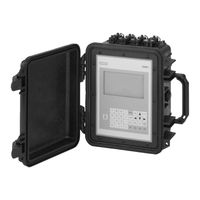
Siemens SITRANS 1010AERWDP Operating Instructions Manual (278 pages)
Ultrasonic Flowmeters Portable Flowmeter
Brand:
Siemens
| Category:
Measuring Instruments
| Size: 2.75 MB
Table of Contents
Table of Contents
37
1 Introduction
45
About this Field Manual
45
Conventions
45
General Installation Menu Notes
45
Introducing the FUP 1010P/WDP Flowmeter
46
Portable Configurations
46
Standard Portable Features
47
Performance
49
Integral Datalogger
49
Analog Outputs
49
Alarm Functions
50
Meter Types
50
Dual Channel Flow
50
Dual Path Flow
50
CH 1+2 or CH 1-2 (Arithmetic) Flow
50
Thickness Gauge
50
Channel Functions
51
Transit-Time Mode
51
Clamp-On
51
Flow Tube
51
Clamp-On Spool
51
Reflexor Mode
51
Getting Started
52
Important Safety Considerations
52
Flowmeter Installation Steps
52
Typical System- 1010P Portable Flowmeter Installation
53
The 1010P Keypad
54
Keypad Function Chart
54
Introduction to the 1010P Menu Screens
54
How to Use the Installation Menu
55
Accessing and Leaving the Menu
56
How to Enter Data
56
Selecting Items from an Option List
57
Multiple Select Option Lists
58
Entering Numeric Data
58
Entering Alphanumeric Strings
59
The Meter Type Menu
59
Dual Channel Flow
60
Dual Path Flow
60
Channel 1+2 and Channel 1-2
60
Multi-Channel Meter Types
61
Arithmetic Operation
61
Multi-Path Operation
61
Selecting a Meter Type
62
Creating a New Site Setup
63
Battery Operation
65
The Charge Indicator LED
65
Forming the Battery (Optimizing Operating Time)
66
How to Use the Battery Charger
66
1015BC-1 Battery Charger
66
1015BC Power Adapter/Charger
68
1010DP Dual-Channel Portable Flowmeter, Rear View
69
1010DP Input/Output Terminals
70
1010WDP Portable Flowmeter, Rear View
71
1010WDP Input/Output Terminals
72
1010WP Single Channel Weatherproof Portable Flowmeter
73
1010WP Input/Output Terminals
74
Using FASTSTART Setup
75
Choosing the Pipe Class/Size
75
Picking and Installing the Transducers
76
2 The 1010P Installation Menu
79
The Channel Setup Menu
80
Channel Setup Menu Structure
80
How to Recall a Site Setup
80
How to Enable and Disable a Measurement Channel
81
How to Create/Name a Site Setup
82
How to Enable/Disable Site Security
82
How to Delete a Site Setup
83
How to Save/Rename a Site Setup
83
The Pipe Data Menu
84
Pipe Data Menu Structure
85
How to Select a Pipe Class
86
How to Select a Pipe Size
86
How to Enter the Pipe OD (In. or MM.)
87
How to Select a Pipe Material
87
How to Enter the Wall Thickness
87
Liner Material
88
Liner Thickness
88
The Application Data Menu
88
Application Data Menu Structure
89
How to Select a Liquid Class
90
How to Edit the Estimated Vs (Liquid Sonic Velocity)
91
How to Edit the Viscosity (Cs) Setting
91
How to Edit the Density (SG) Setting
91
How to Select a Pipe Temperature Range
92
Pipe Configuration
92
Pipe Configuration Menu Structure
93
Pipe Configuration Option List Definitions
93
The Pick/Install XDCR (Transducer) Menu
94
Pick/Install Xdcr Menu Structure
95
How to Select a Transducer Model
95
How to Select a Transducer Size
96
How to Select a Transducer Mount Mode
96
Reviewing the Spacing Method
97
How to Use the Spacing Offset
97
Letter Index (1011 Transducer) - Letter and Number Index
98
Ducer)
98
The 1011 Transducer
98
The 990 Transducer
98
The Ltn Menu Cell
98
The Number Index Menu Cell
98
How to Use [Install Completed?]
99
Force Transmit Procedure
100
The Empty Pipe Set Menu
103
How to Use the Actual MTY Command
103
How to Use the Mtymatic Command
103
How to Use the Set Empty Command
104
Zero Flow Adjust Menu
104
Actual Zero
104
Autozero
104
Reversamatic
104
Using Actual Zero
105
Using Reversamatic
105
Zeromatic
105
Zeromatic (Optional Function)
106
The Operation Adjust Menu
108
Operation Adjust Menu Structure
108
Damping Control
109
Deadband Control
109
Memory/Fault Set
110
Memory Delay (Sec)
110
Reflexor Zero/Fault Set (Reflexor Mode Only)
110
The Flow/Total Units Menu
111
Flow/Total Units Menu Structure
111
Flow Display Range
112
Flow Time Units
112
Flow Volume Units
112
Flow Display Scale
113
Total Volume Units
113
Totalizer Scale
113
Total Resolution
114
Totalizer Mode
114
Batch/Sample Total
115
Totalizer Controls
115
The Data Span/Set/Cal Menu
116
Data Span/Set/Cal Menu Structure
116
Span Data
117
Max Flow
118
Max Temperature
118
Max Vs M/S
118
Min Flow
118
Min Vs M/S
118
Min Temperature
119
Set Alarm Levels
119
High Flow
119
High Temperature
119
Low Flow
119
Low Temperature
119
Aeration
120
Interface Vs (M/S) Meters-Per-Second
120
Makeup Latch
120
Calibrate Flowrate
121
Kc Calibration
121
Multipoint Calibration
122
The Stripchart Setup Menu
123
Stripchart Setup Menu Structure
123
Data Display
124
Select Data
124
Stripchart Clear
125
The Datalogger Setup Menu
125
Datalogger Setup Menu Structure
126
Time Base
125
Datalogger Data
127
Datalogger Mode
127
Log Time Interval
128
Datalogger Events
129
Display Datalogger
129
The I/O Data Control Menu
130
I/O Data Control Menu Structure
131
Analog out Setup
131
Analog out Setup Data Categories
131
System 1010 Analog Outputs
131
Assigning Io Output Functions
132
Assigning Pgen Output Functions
132
Assigning Vo Output Functions
132
Pulse Output (Pgen Wiring)
132
Relay Setup
132
Assigning Relay 1 and 2 Functions
133
Relay Option List
133
Analog Input Setup (Optional Function)
133
Setting up the Analog Current Input
134
The Diagnostics Data Menu
134
Diagnostic Data Menu Structure
135
Flow Data Menu
136
Flow Data Menu Items
137
Vs M/S
137
Ancal
138
Hiflow and Loflow
138
Main Diagnostics Screen
136
Main Diagnostic Menu Description
136
The Application Info Menu
139
Application Info Menu Items
139
The Liquid Data Menu
139
Liquid Data Menu Items
140
The Site Setup Data Menu
140
Site Setup Menu Items
140
Introduction to [HF] Menu Item
141
Using the [HF] Menu Item
141
Manual" Adjustment Procedure
142
Automatic" Adjustment Procedure
143
The Test Facilities Menu
144
Makeup
144
Test Facilities Commands
144
Detection Modes
145
Test Facilities Graph Screen
145
Correlated Plot
146
Diagnostic Text Display
146
Entering the Diagnostic Graph Screen
146
Time Base Control
146
Command Modes
147
Digital Damping Controls: (Hot Key 1 and 2)
147
Transit Time Adjustment: (Hot Key 3)
147
Envelope Threshold Adjustment: (Hot Key 5 & 6)
148
Zero Crossover Adjustment: (Hot Key 4)
148
Description of Graph Screen Text Display Parameters
149
Hot Key Summary
149
Signal Masking Function: (Hot Key 7)
149
Troubleshooting Tips
150
Flow Computer Messages
150
Using the "F4" Reset Sequence
151
Troubleshooting with Transducer Test Blocks
153
Using the 1012TB-1 and 2 Test Blocks
153
Using the 996PSP Pipe Simulator
154
If a Pipe Simulator/Test-Block Test Fails
156
Checklist for 1010 Startup & Performance
157
Guide to a Smooth Installation
157
Optimization/Correction of Problems
158
3 Hardware Installation Guide
163
Preparing to Mount the Transducers
163
How to Identify 1011 Transducers and Mounting Hardware
163
Selecting a Location for Clamp-On Transducers
163
Clamp-On Transducer Mounting Modes
164
Preparing the Pipe
165
Reflect Mode with EZ Clamp and Spacer Bar
166
Direct Mode with EZ Clamp and Spacer Bar Only
167
Reflect Mode - Mounting Frames and Spacer Bar
171
Reflect Mode with Spacer Bar Only
172
Direct Mode - Mounting Frames, Spacer Bar & Spacing Guides
174
Using 1012T Mounting Tracks
178
Installing a 1012T Mounting Track in Reflect Mode
178
Installing a 1012T Mounting Track in Direct Mode
180
Mounting Temperature Sensors (Optional)
182
4 The Meter Facilities Menu and Graphic Display Screens
185
Preferred Units
185
The Table Setups Menu
186
Pipe Table
186
Pipe Table Menu Structure
186
Create/Edit Pipe
187
Delete Pipe
188
Transducer Type Menu
188
Transducer Type Menu Structure
189
The Datalogger Control Menu
190
Datalogger Control Menu Structure
190
Display Datalogger
190
Output Datalogger
191
Circular Memory
191
Est Log Time Left
192
Clear Datalogger
192
The Memory Control Menu
192
Data Memory Left
192
Memory Map
192
Defragment
192
The Analog Output Trim Menu
193
Analog Output Trim Menu Structure
193
Current Output Trim (Io1 and Io2)
193
Voltage Output Trim (Vo1 and Vo2)
193
Pgen Output Trim (Pgen 1 and Pgen 2)
194
The RTD Calibrate Menu (Optional)
194
RTD Calibrate Menu Structure
195
RTD Calibration by Data Entry
195
Ice Bath RTD Calibration
195
The Clock Set Menu
196
Clock Set Menu Structure
196
Date
196
Time
196
Setup
197
Setup Menu Structure
197
Baud Rate
197
Parity
198
Data Bits
198
Line Feed
198
Network ID
199
RTS Key Time
199
Backlight
199
System Info
200
The 1010P Graphic Display Screens
200
5 System 1010P Application Notes
203
To Obtain Technical Assistance
203
Considerations for Critical Applications
203
Pipe Considerations for Clamp-On Transducers
204
Pipe Dimensions
204
Picking the Appropriate Transducer
204
Flow Velocity Range
204
Overview of System Performance
205
Accuracy
205
Repeatability
205
Data Stability
205
Data Scatter
205
Data Drift
206
Flow Conditions
206
Low Flow Rates
206
Flow Data Scatter and Damping
206
System 1010P Damping and Slewing Controls
206
Time Average
206
Smartslew
206
Notes on Liquid Conditions
207
Erroneous Liquid Parameter Specification
207
Liquid Compatibility
207
Aeration
207
Slurries
208
Two-Phase Liquids
208
Viscous Liquids
208
Temperature and Pressure Ratings
208
Overview of System 1010P Memory Resources
208
Reference Tables
209
Recommended Sonic Coupling Compounds
211
System 1010 Reynolds Compensation Factors
212
Terminology Chart
213
The Dual-Channel Menu Chart
215
The Meter Type Menu
215
The Meter Facilities Menu
215
The Clamp-On Menu
217
6 Operating System 1010P with Flow Tubes
221
General Installation Guidelines
221
Liquid Applicability and Compatibility
221
Selecting the Right Flow Tube
222
Flow Tube Mounting Location
222
Flow Data Scatter and Damping
223
Considerations for Critical Applications
223
Overview
224
Setup Procedure
224
Specifications - CPVC Flow Tube
229
Specifications - KYNAR PVDF Flow Tube
229
Specifications - TEFLON PFA Flow Tube
230
Specifications - 316 Stainless Steel Flow Tube
230
Additional Installation Notes
231
7 The System 1010 Reflexor Flowmeter
233
Reflexor Installation Steps
233
Select a Transducer Set for Use by Reflexor
233
Select the Transducer Mounting Location
234
Mounting the Transducer
235
Access the Install Xdcr (Transducer) Menu
236
Connection of Transducer Cables
236
Installing Reflexor Operating Mode
236
Select Reflexor Operating Mode
236
The Spectra Display Screen
237
Cursor Use on the Spectra Graph
238
How to Use Spectra Graph Data and Controls
238
Available Adjustments to Spectra Graph
239
Reflexor Diagnostic Data
240
Display of "F" at no Flow Conditions
241
Other Menu Entries
241
Selection of Liquid Composition
241
Introduction
243
8 The Thickness Gauge
243
The Wall Thickness Screen
243
The Thickness Transducer
244
Selecting the Thickness Gauge
245
Calibrating the Thickness Gauge
246
Manual Calibration of Thickness Gauge
249
Modify Vpl (Ips)
249
Select Material
249
Zero Set (Usecs)
249
Data Lock Level
250
Longitudinal Sound Velocity (Vpl) of Various Pipe Materials
250
Reset Defaults
250
Troubleshooting Guide
250
Measuring the Pipe Wall Thickness
251
APPENDIX A Engineering Drawings
255
Index
263
Advertisement
Advertisement
Related Products
Siemens multiranger 100
Siemens Ardoptix PT 140 AF4
Siemens Ardoptix PT 140 AF1
Siemens Ardoptix PT 143 AF4
Siemens Ardoptix PT 143 AF1
Siemens 13-xx-ST-SBT Series
Siemens VDO E-Tacho 1323.01
Siemens VDO E-Tacho 1323.02
Siemens VDO E-Tacho 1323.03
Siemens MPA 10 AF1
Siemens Categories
Industrial Equipment
Controller
Control Unit
Oven
Washer
More Siemens Manuals
Login
Sign In
OR
Sign in with Facebook
Sign in with Google
Upload manual
Upload from disk
Upload from URL