Sign In
Upload
Manuals
Brands
Siemens Manuals
Measuring Instruments
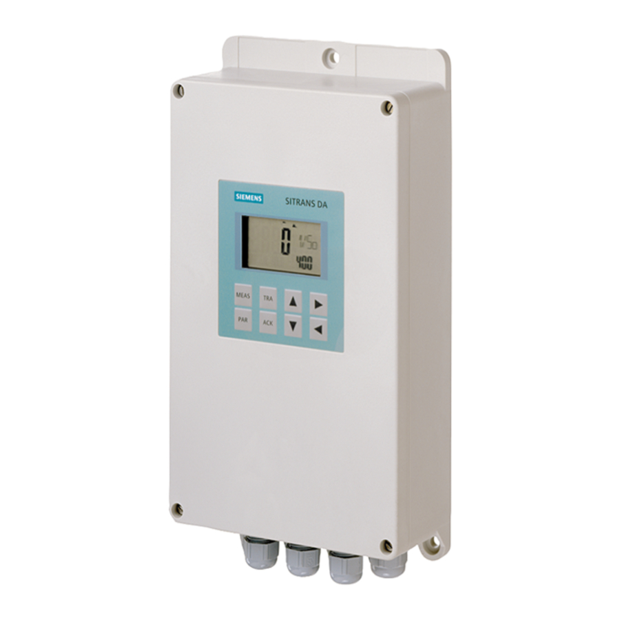
SITRANS DA400
Siemens SITRANS DA400 Manuals
Manuals and User Guides for Siemens SITRANS DA400. We have
4
Siemens SITRANS DA400 manuals available for free PDF download: Operating Instructions Manual
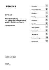
Siemens SITRANS DA400 Operating Instructions Manual (104 pages)
Process monitoring for oscillating positive displacement pumps
Brand:
Siemens
| Category:
Measuring Instruments
| Size: 2.61 MB
Table of Contents
Table of Contents
3
Introduction
7
Purpose of this Documentation
7
History
7
Further Information
8
CE Label
9
General Safety Notes
11
General Information
11
Correct Usage
11
Laws and Directives
11
Measures
12
Qualified Personnel
12
Description
13
Applications
13
Operation
13
Layout
14
Device Structure
14
Structure of the Nameplate
15
Mode of Operation
16
Measuring Principle
16
Principle of Measurement with Trigger Sensor
19
Sensor Operation
20
Operation of the Electronics
21
Mounting
23
Safety Information for Installation
23
Mounting the Device
24
Installation Notes for Acoustic Emission Sensors
24
Installation Notes for Trigger Sensors
25
Connecting
27
Safety Notes and Conditions
27
Terminal Assignment
28
Cable Gland
29
Connecting Acoustic Emission Sensors
30
Connecting Digital Outputs
30
Connecting Signal Inputs
31
Connecting PROFIBUS DP
33
Connecting the Power Supply
34
Operation
35
Overview of Digital Display and Buttons
35
Digital Display
37
Measuring Menu
38
Overview and Digital Display in the Measuring Menu
38
Measurement Channel List
39
Operating the Measuring Menu
39
Acoustic Channels
41
Measuring Mode
41
Simulation Mode
43
Test Mode
45
Universal Inputs
47
Analog Input
47
Digital Input
48
Trigger Input
49
Parameter Menu
50
Parameter Menu Overview
50
Parameter List
51
Setting Parameters
54
Displaying the Software Version
54
Parameter Lock
55
Trace Menu
56
Trace Menu Overview
56
Trace Menu List
57
Displaying and Resetting Timers
59
Examples
60
Example Acoustic Channel 1
60
Example Universal Input 1
61
Signal Processing
63
Evaluating Acoustic Channels
63
Evaluation of Universal Inputs
66
Universal Input Evaluation Overview
66
Evaluation of Analog Current Signals
66
Evaluation of 24 V Digital Signals
68
Evaluation of Digital Signals in Line with NAMUR
69
Evaluation Trigger Signal
70
Processing Input Faults
73
Activation of Digital Outputs
73
Alarm Acknowledgement
76
Trace Function
77
Commissioning
79
Overview
79
Recommendation for the Selection of Parameters
80
Preparation
80
Measuring Sensitivity of the Acoustic Channels Via Parameters P.1 to
81
Main Alarm Threshold Via Parameters P.6, P.8, P.10 and
81
Pre-Alarm Threshold Via Parameters P.5, P.7, P.9 and
81
Response Time Via Parameter
82
Alarm Storage Via Parameter
82
Application Via Parameter
82
Number of Strokes of the Pump Via Parameter
83
Closing Angles of Suction Valves P.45 to
83
Check Installation and Configuration
83
Commissioning after a Repair
83
Technical Data
85
Technical Data for the Device
85
Application-Specific Use Limits
87
Technical Data for the Sensor
87
Dimension Drawings
89
Dimension Drawing of the Device
89
Dimension Drawing of the Sensor
90
Profibus Dp
91
Overview
91
Measured Value and Status Format
94
Meaning of 8 Byte Binary Status Signals
94
Read/Write Parameters
97
Examples for PROFIBUS DP
98
Index of Objects
99
Index
103
Advertisement
Siemens SITRANS DA400 Operating Instructions Manual (94 pages)
Process monitoring
Brand:
Siemens
| Category:
Measuring Instruments
| Size: 3.11 MB
Table of Contents
Table of Contents
3
1 Introduction
7
Purpose of this Documentation
7
Further Information
7
History
8
CE Label
8
2 General Safety Notes
9
General Information
9
Correct Usage
9
Laws and Directives
9
Measures
10
Qualified Personnel
10
3 Description
11
Application Range
11
Operation
11
Design
12
Device Structure
12
Structure of the Nameplate
13
Mode of Operation
14
Principle of Measurement
14
Sensor Operation
15
Operation of the Electronics
16
4 Assembly
19
Safety Information for Installation
19
Mounting the Device
19
Mounting the Acoustic Emission Sensor
20
5 Connecting
23
Safety Notes and Conditions
23
Terminal Assignment
25
Cable Gland
26
Connecting Structure-Borne Sound Sensors
27
Connecting the Digital Outputs
28
Connecting Signal Inputs
29
Connect PROFIBUS PA
31
Connecting the Power Supply
32
Connect the Ground
33
6 Operation
35
Overview of Digital Display and Buttons
35
Digital Display
37
Measuring Menu
38
Overview and Digital Display in the Measuring Menu
38
Measurement Channel List
39
Operating the Measuring Menu
39
Acoustic Channels
41
Measuring Mode
41
Simulation Mode
42
Test Mode
44
Universal Inputs
45
General
45
Analog Input
46
Digital Input
47
Parameter Menu
48
Parameter Menu Overview
48
Parameter List
49
Setting Parameters
51
Displaying the Software Version
51
Parameter Lock
52
Trace Menu
52
Trace Menu Overview
52
Trace Menu List
54
Displaying and Resetting Timers
56
Examples
56
Example Acoustic Channel 1
56
Example Universal Input 1
58
7 Signal Processing
59
Evaluating Acoustic Channels
59
Universal Input Evaluation
62
Universal Input Evaluation Overview
62
Evaluation of Analog Current Signals
62
Evaluation of 24 V Digital Signals
64
Processing Input Faults
65
Activation of Digital Outputs
66
Alarm Acknowledgement
69
Trace Function
70
8 Commissioning
73
Overview
73
Recommendation for Selecting Parameters
74
Preparation
74
Damping Using Parameters P.41, P.42, P.43 and
74
Main Alarm Threshold Via Parameters P.6, P.8, P.10 and
74
Pre-Alarm Threshold Via Parameters P.5, P.7, P.9 and
75
Response Time Via Parameter
75
Alarm Storage Via Parameter
75
Check Installation and Configuration
75
Commissioning after a Repair
75
9 Technical Data
77
Device Technical Data
77
Sensor Technical Data
82
10 Dimension Drawings
85
Dimension Drawing of the Device
85
Dimension Drawing of the Sensor
86
11 Profibus Pa
87
System Integration
87
Projection
88
Expanded Diagnosis
92
Index
93
Siemens SITRANS DA400 Operating Instructions Manual (86 pages)
Process monitoring SITRANS DA400 for oscillating positive displacement pumps with protection against explosion
Brand:
Siemens
| Category:
Measuring Instruments
| Size: 2.82 MB
Table of Contents
Table of Contents
3
1 Introduction
7
Purpose of this Documentation
7
History
7
Further Information
7
CE Label
8
2 General Safety Notes
9
General Information
9
Correct Usage
9
Laws and Directives
9
Measures
10
Qualified Personnel
10
3 Description
11
Applications
11
Operation
11
Layout
12
Device Structure
12
Structure of the Nameplate
13
Mode of Operation
14
Measuring Principle
14
Sensor Operation
16
Operation of the Electronics
17
4 Mounting
19
Safety Information for Installation
19
Mounting the Device
19
Installation Notes for Acoustic Emission Sensors
20
5 Connecting
21
Safety Notes and Conditions
21
Terminal Assignment
22
Cable Gland
23
Connecting Structure-Borne Sound Sensors
24
Connecting the Digital Outputs
25
Connecting Signal Inputs
25
Connect PROFIBUS PA
27
Connecting the Power Supply
28
Connect the Ground
29
6 Operation
31
Overview of Digital Display and Buttons
31
Digital Display
32
Measuring Menu
33
Overview and Digital Display in the Measuring Menu
33
Measurement Channel List
34
Operating the Measuring Menu
34
Acoustic Channels
35
Measuring Mode
35
Simulation Mode
36
Test Mode
38
Universal Inputs
40
Analog Input
40
Digital Input
41
Parameter Menu
42
Parameter Menu Overview
42
Parameter List
43
Setting Parameters
45
Displaying the Software Version
46
Parameter Lock
46
Trace Menu
47
Trace Menu Overview
47
Trace Menu List
47
Displaying and Resetting Timers
49
Examples
50
Example Acoustic Channel 1
50
Example Universal Input 1
51
7 Signal Processing
53
Evaluating Acoustic Channels
53
Evaluation of Universal Inputs
56
Universal Input Evaluation Overview
56
Evaluation of Analog Current Signals
56
Evaluation of 24 V Digital Signals
57
Processing Input Faults
58
Activation of Digital Outputs
59
Trace Function
61
Alarm Acknowledgement
63
8 Commissioning
65
Overview
65
Recommendation for the Selection of Parameters
66
Preparation
66
Measuring Sensitivity of the Acoustic Channels Via Parameters P.1 to
67
Main Alarm Threshold Via Parameters P.6, P.8, P.10 and
67
Pre-Alarm Threshold Via Parameters P.5, P.7, P.9 and
67
Response Time Via Parameter
68
Alarm Storage Via Parameter
68
Application Via Parameter
68
Number of Strokes of the Pump Via Parameter
69
Check Installation and Configuration
69
Commissioning after a Repair
69
9 Technical Data
71
Device Technical Data
71
Application-Specific Use Limits
75
Sensor Technical Data
75
10 Dimension Drawings
77
Dimension Drawing of the Device
77
Dimension Drawing of the Sensor
78
11 Profibus Pa
79
System Integration
79
Projection
79
Expanded Diagnosis
82
Index
85
Advertisement
Siemens SITRANS DA400 Operating Instructions Manual (68 pages)
Process monitoring with protection against explosion
Brand:
Siemens
| Category:
Diagnostic Equipment
| Size: 3.39 MB
Table of Contents
Table of Contents
3
1 Introduction
5
Purpose of this Documentation
5
Further Information
5
CE Label
6
2 General Safety Notes
7
General Information
7
Correct Usage
7
Laws and Directives
7
Measures
8
Qualified Personnel
8
3 Description
9
Applications
9
Operation
9
Structure
10
Device Structure
10
Structure of the Nameplate
11
How It Works
12
Measuring Principle
12
Sensor Operation
12
Operation of the Electronics
13
4 Assembly
15
Safety Information for Installation
15
Mounting
15
5 Connecting
17
General Information and Procedures
17
Terminal Assignment
19
Cable Gland
19
Connecting the Sensors
20
Connecting the Digital Outputs
21
Connect the Signal Inputs
22
Connect PROFIBUS PA
24
Connecting the Power Supply
25
Connect the Ground
26
6 Operation
29
Overview of Operation
29
Digital Display
30
Measuring Menu
31
Overview
31
Acoustic Channels
31
Universal Inputs
33
Parameter Table
33
Setting Parameters
36
Parameter Lock
37
Trace Menu
38
Trace Menu Table
38
Displaying and Resetting the Timer
39
7 Evaluating and Processing Signals
41
Evaluation of Acoustic Channels
41
Evaluation of Universal Inputs
42
Universal Input Evaluation Overview
42
Evaluation of Analog Current Signals
43
Evaluation of 24 V Digital Signals
44
Processing of Input Faults
45
Actuation of Digital Outputs
46
Trace Function
48
Acknowledgement
49
8 Starting up
51
Overview
51
Commissioning after Repairs
53
9 Technical Data
55
Technical Data for the Device
55
Sensor for Technical Data
58
10 Dimension Diagrams
61
Sitrans Da400
61
Sensor
62
11 Profibus Pa
63
System Integration
63
Projection
63
Expanded Diagnosis
66
Advertisement
Related Products
Siemens DCA Vantage
Siemens interranger DPS300
Siemens DESIGO PX -U Series
Siemens sitrans LU01
Siemens SITRANS F M MAG 1100
Siemens SITRANS F M MAG 3100
Siemens SITRANS MAG 5100W
Siemens SITRANS F M MAG 5000
Siemens SITRANS F M MAG 6000
Siemens Sitrans LR250
Siemens Categories
Industrial Equipment
Controller
Control Unit
Oven
Washer
More Siemens Manuals
Login
Sign In
OR
Sign in with Facebook
Sign in with Google
Upload manual
Upload from disk
Upload from URL