Sign In
Upload
Manuals
Brands
Siemens Manuals
Measuring Instruments
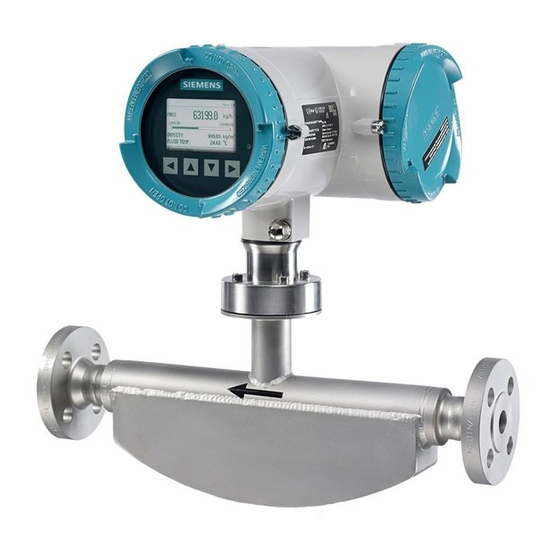
SITRANS FC330
Siemens SITRANS FC330 Flowmeter System Manuals
Manuals and User Guides for Siemens SITRANS FC330 Flowmeter System. We have
1
Siemens SITRANS FC330 Flowmeter System manual available for free PDF download: Operating Instructions Manual
Siemens SITRANS FC330 Operating Instructions Manual (280 pages)
Coriolis Flowmeters
Brand:
Siemens
| Category:
Measuring Instruments
| Size: 17.23 MB
Table of Contents
Table of Contents
3
1 Introduction
9
Purpose of this Documentation
9
Document History
9
Product Compatibility
10
Items Supplied
10
Checking the Consignment
12
Security Information
12
Transportation and Storage
13
Notes on Warranty
13
2 Safety Notes
15
Preconditions for Use
15
Laws and Directives
15
FCC Conformity
16
Conformity with European Directives
16
Requirements for Special Applications
17
Use in Hazardous Areas
17
Installation in Hazardous Areas
19
Maximum Temperature Specifications for Use in Hazardous Areas
20
3 Description
21
Overview
21
Design
22
Versions
22
Sensor Design
23
Transmitter Design
24
Wall Mount Housing Transmitter Exploded View
26
Device Identification
27
Approvals
32
Features
33
Applications
35
4 Installing/Mounting
37
Basic Safety Notes
37
Installation Location Requirements
39
Proper Mounting
40
Installation Instructions
41
Transmitter Installation
41
Remote Field Mount
41
Wall Mount Housing
42
Turning the Transmitter (Compact Version)
45
Turning the Transmitter (Remote Version)
46
Turning the Local Display
48
Sensor Installation
49
Determining a Location
49
Orientation of the Sensor
50
Installation in a Drop Line
52
Mounting the Sensor
52
Hydrostatic Testing
54
Installing with Insulation
54
Disassembly
55
5 Connecting
57
Basic Safety Notes
57
Connecting FC330
60
Cable Requirements
61
Transmitter Power Supply and I/Os Connection
62
Connecting the DSL and the Transmitter
62
Preparing for the Transmitter Connections
65
Connecting the Current HART, CH1
67
Connecting the Modbus (CH1)
69
Connecting the Profibus (CH1)
71
Connecting Channels 2 to 4
72
Input/Output Configuration
74
Connecting the Power Supply - Field Mount
75
Connecting the Power Supply - Wall Mount
77
Finishing the Transmitter Connection
78
Instructions Specific to Hazardous Area Installations
79
Wiring in Hazardous Areas
79
6 Commissioning
81
Basic Safety Notes
81
Warnings
83
General Requirements
84
Local Commissioning Via HMI
84
Local Display
84
Wizard Introduction
85
Initial Startup
85
Zero Point Adjustment
86
Wizards
88
Quick Commissioning Wizard (Menu Item 1.1)
88
Zero Point Adjustment Wizard (Menu Item 1.2)
90
Process Values Wizard (Menu Item 1.3)
92
Inputs and Outputs Wizard (Menu Item 1.4)
94
Gas Application Wizard (Menu Item 1.5)
99
Pulsating Flow Wizard (Menu Item 1.6)
100
Dosing Application Wizard (Menu Item 1.7)
101
Remote Commissioning with PDM
102
7 Operating
103
Local Operation (HMI)
103
Display View Structure
104
Access Control
109
Operation View
110
Measurement Views
111
Operating Views
114
Alarm Views
115
Diagnostic Views
117
Navigation View
117
Parameter View
119
Remote Operation
123
Overview of Device Configuration Software
123
Simatic Pdm
123
8 Parameter Assignment
127
Upper Scaling Settings
127
Functions
127
Process Values
127
Zero Point Adjustment
131
Low Flow Cut-Off
132
Empty Tube Monitoring
132
Process Noise Damping
133
Inputs and Outputs
134
Current Output
135
Pulse Output
140
Frequency Output
141
Redundancy Mode (Frequency)
142
Digital Output
144
Input
144
Totalizers
145
Dosing
145
Dosing Control Configuration
147
Valve Control Configuration
148
Dosing Operation
153
Fault Handling
153
Audit Trail Logging
154
Diagnostic Log
154
Custom Unit
155
Sensorflash
155
Datalogging on Sensorflash
156
Process Peak Values on Sensorflash
156
Simulation
156
Maintenance
157
9 Service and Maintenance
159
Basic Safety Notes
159
Recalibration
160
Cleaning
160
Maintenance and Repair Work
161
Service Information
164
Replacing the Device
165
Ordering of Spare Parts
165
Return Procedure
165
Disposal
166
Ex-Approved Products
166
10 Diagnostics and Troubleshooting
167
Device Status Symbols
167
Fault Codes and Corrective Actions
171
Sensor Diagnostics
171
Transmitter Diagnostics
176
Operation Troubleshooting
189
Copying the Application Setup from One Device to Another
189
Updating the Firmware
189
Troubleshooting Sensor-Related Problems
190
11 Technical Data
195
Power
195
Performance
195
Interface
197
Modbus Interface
197
HART Interface
197
Inputs
198
Outputs
198
Construction
200
Sensor Design
201
Sensor Cable Specifications HART
202
Operating Conditions
204
Process Variables
205
Bus Communication
205
Certificates and Approvals
206
Sensorflash
206
Ped
207
Pressure - Temperature Ratings
211
Pressure - Temperature Ratings (Stainless Steel Sensors)
212
Pressure - Temperature Ratings (Nickel Alloy Sensors)
214
12 Dimension Drawings
217
Sensor Dimensions
217
Stainless Steel - Standard
218
Stainless Steel Polished - Hygienic Versions
219
Nickel Alloy
220
Transmitter Dimensions
221
Wall Mount Enclosure Dimensions
222
Mounting Bracket Dimensions
223
Technical Reference
225
Theory of Operation
225
A.1 Theory of Operation
225
Sensor Dimension Dependent Default Settings
226
Mass Flow: Sensor Dimension Dependent Default Settings (Process Values)
226
Standard Volume Flow: Sensor Dimension Dependent Default Settings (Process Values)
228
Volume Flow: Sensor Dimension Dependent Default Settings (Process Values)
229
Fraction: Sensor Dimension Dependent Default Settings (Process Values)
231
Zero Point Adjustment: Sensor Dimension Dependent Default Settings (Process Values)
233
HART Communication
235
Mode of Operation HART Function
235
HMI Menu Structure
237
Main Menu
237
C.1 Main Menu
237
Menu Item 2.1: Sensor
239
Menu Item 2.2: Process Values
239
Menu Item 2.3: Totalizers
243
Menu Item 2.4: Inputs and Outputs
244
Menu Item 2.5: Dosing
251
Menu Item 2.7: Date and Time
256
Menu Item 2.8: Local Display
257
Menu Item 3.1: Identification
259
Menu Item 3.2: Diagnostic Events
260
Menu Item 3.3: Maintenance
261
Menu Item 3.4: Diagnostics
261
Menu Item 3.5: Peak Values
263
Menu Item 3.6: Characteristics
263
Menu Item 3.7: Sensorflash
264
Menu Item 3.8: Simulation
265
Menu Item 3.9: Audit Trail
266
Menu Item 3.10: Self Test
266
Menu Item 3.11: Resets
267
Menu Item 3.12: Firmware Update
267
Menu Item 4: Communication
267
C.19 Menu Item 3.11: Resets
267
Menu Item 5: Security
270
Zero Point Adjustment
271
Certificates and Support
275
Certificates
275
QR Code Label
275
Technical Support
275
E.1 Certificates
275
Index
277
Advertisement
Advertisement
Related Products
Siemens FC300
Siemens SITRANS FC310
Siemens SITRANS FC430
Siemens FCA2002-A1
Siemens FCA2008-A1
Siemens FCL2001-A1
Siemens FCL2003-A1
Siemens FCI2008-A1
Siemens FCC2002-A1
Siemens FCI2006-C1
Siemens Categories
Industrial Equipment
Controller
Control Unit
Oven
Washer
More Siemens Manuals
Login
Sign In
OR
Sign in with Facebook
Sign in with Google
Upload manual
Upload from disk
Upload from URL