Sign In
Upload
Manuals
Brands
Sony Manuals
Camcorder
DSR-250
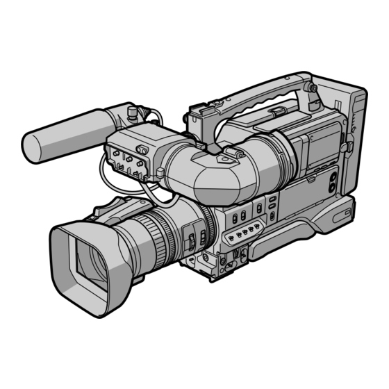
User Manuals: Sony DSR-250 Professional Camcorder
Manuals and User Guides for Sony DSR-250 Professional Camcorder. We have
5
Sony DSR-250 Professional Camcorder manuals available for free PDF download: Service Manual, Operating Instructions Manual, Brochure & Specs, Product Information
Sony DSR-250 Service Manual (322 pages)
Brand:
Sony
| Category:
Camcorder
| Size: 49.69 MB
Table of Contents
Memory Stick
2
Supplied Accessories
2
Table of Contents
3
Schematic Diagrams
4
Service Note
8
Service Note
9
Self-Diagnosis Function
9
Self-Diagnosis Display
9
Service Mode Display
9
Display Method
9
Switching of Backup no
9
End of Display
9
Self-Diagnosis Code Table
10
General
11
Auto Logo Insert for Copyright Protection
58
Disassembly
62
Lcd Section
63
Transformer Unit
63
Carrying Handle Section (Th-010, Me-019 Boards, Vf Shoe Base)
64
Vf Section (Main, Sub Boards)
65
Cabinet (R) Block Assembly (Sw-343 Board)
66
Hinge Section (Hinge Assembly, Fp-241 Flexible Board)
67
Cabinet (L) Assembly, Mechanism Deck
68
Mechanism Deck Service Position
68
Boards
69
Board
70
Lens Block Assembly
71
Control Switch Block (CF-1044)
71
Lens Block Assembly (Lens Cabinet (R))
72
Boards
72
Flexible Boards Location
77
Block Diagrams
78
Overall Block Diagram (1/5)
78
Overall Block Diagram (2/5)
79
Overall Block Diagram (3/5)
80
Overall Block Diagram (4/5)
81
Overall Block Diagram (5/5)
82
Ch1/Ch2 MIC Amp
142
DC-DC Converter
144
DC out
144
Light
146
Waveforms
147
Mounted Parts Location
151
Adjustments
159
Before Starting Adjustment
159
Adjusting Items When Replacing Main Parts and Boards
160
Camera Section Adjustment
162
Preparations before Adjustment
162
List of Service Tools
162
Preparations
164
How to Make the DC Cable
164
Precaution
166
Setting the Switch
166
Order of Adjustments
166
Subjects
166
Initialization of A, B, C, D, E, F, 8 Page Data
167
Modification of C, D, 8 Page Data
167
Page Table
170
Initializing the a Page Data
170
Modification of E, F Page Data
172
Camera System Adjustments
174
Mhz Origin Oscillation Adjustment (VI-156 Board)
174
Zoom Key Center Adjustment
174
HALL Adjustment
175
Offset Adjustment
175
Flange Back Adjustment
177
More than 500M Away)
177
Flange Back Adjustment (1)
177
Flange Back Adjustment (2)
177
Flange Back Check
178
Picture Frame Setting
178
Pre White Balance Data Input
179
Auto White Balance Standard Data Input
179
MAX GAIN Adjustment
180
LV Standard Data Input
180
White Balance ND Filter 1 Compensation
181
White Balance ND Filter 2 Compensation
181
Auto White Balance Adjustment
182
Color Reproduction Adjustment (ND Filter OFF)
182
Color Reproduction Adjustment (ND Filter 1)
183
Color Reproduction Adjustment (ND Filter 2)
183
White Balance Check
184
Steady Shot Adjustment
185
Steady Shot Adjustment (1)
186
Steady Shot Adjustment (2)
187
Lcd System Adjustment
188
VCO Adjustment (PD-126 Board)
188
Bright Adjustment (PD-126 Board)
189
Black Limit Adjustment (PD-126 Board)
189
Contrast Adjustment (PD-126 Board)
190
Center Level Adjustment (PD-126 Board)
190
V-COM Adjustment (PD-126 Board)
191
White Balance Adjustment (PD-126 Board)
191
Mechanical Section Adjustment
192
Adjustment
193
Compartment
193
How to Load/Unload
193
About Mode Selector II
194
Outline
194
Manual Test
194
Step Test
194
Auto Test
194
Mode Selector II Connection
194
Periodic Check
195
Cleaning of Rotary Drum Assembly
195
Cleaning of Tape Path System
195
Periodic Checks
195
Parts Replacement
196
Tape Guide 1/8 and Guide Guard
196
Tape Guide 2/7
196
Capstan Cover
197
Reel Motor
197
Fl Motor Assembly, Gear A, Gear B and Gear CD Assembly
197
Gl Arm S Assembly, Gl Arm T Assembly
198
Assembly
198
MIC Base Guide, MIC Base Assembly and MIC Base Spring
199
Drum Cap, Drum Assembly and Tape Support
199
Pinch Arm Assembly
200
Capstan Motor
200
Pendulum Retainer and Pendulum Arm
200
Assembly
200
Brake Arm S, Ratchet Brake T, Tension
201
Flexible Board (Condensation Sensor)
201
Reel Table Assembly, Idler Gear Aassembly and Idler Gear B
201
Reel Base Retainer, Reel Base T Assembly
202
Cam Motor, Motor Holder
202
Tg2/7 Arm Block, Tg2/7 Band Block and Tension Coil Spring (Tg2)/(Tg7)
203
Sub-Slider Arm, Sub-Slider, Encoder Gear
204
Pinch Slider and Loading Arm Assy
204
Main Slider, Main Slider Arm and Pendulum Stopper Assembly
206
Board and Encoder Retainer
207
Components of Gl Arm S/T Assembly
208
Components of MIC Base Assembly (Fp-104 Flexible Board, MIC Base)
208
Components of Drum Assembly
209
(Motor Fpc Assembly, Elastic Connector)
209
Components of Pinch Arm Assembly (Tape Retainer, Compression Coil Spring)
209
Components of Tg2/7 Arm Assembly (Et Magnet, Magnet Holder)
209
Check and Adjustment
210
Reel Table Height Check and Adjustment
210
Preparation before Check
211
Check and Adjustment
211
Tg2/7 Height Check and Adjustment
212
Preparation before Check
212
Check and Adjustment
212
Fwd/Rvs Position Check and Adjustment
212
Electric Tension Regulator Check and Adjustment of Tg2/7 Arm
213
Preparation before Check
213
Check and Adjustment
213
Adjustment
213
Preparation before Check
214
Check and Adjustment
214
Preparation for Adjustment and Tape Path Check
214
Track Adjustment and Check
215
(Checking the RF Waveform)
215
Track Check
215
Cue/Rev Check
216
Curl Check and Adjustment
216
Rising Check
217
Video Section Adjustments
218
Preparations before Adjustments
218
Equipment Required
218
Precautions on Adjusting
219
How to Enter Record Mode Without
220
Cassette
220
How to Enter Playback Mode Without
220
Adjusting Connectors
220
Connecting the Equipment
220
Alignment Tapes
221
Input/Output Level and Impedance
221
System Control System Adjustment
222
Initialization of A, B, C, D, E, F, 8 Page Data
222
Serial No. Input
222
Company ID Input
222
Battery End Adjustment
224
Servo and Rf System Adjustment
225
Cap FG Duty Adjustment (VI-156 Board)
225
PLL F & LPF F Adjustment (VI-156 Board)
225
Switching Position Adjustment (VI-156 Board)
226
AGC Center Level and APC & AEQ Adjustment
226
Preparations before Adjustments
226
AGC Center Level Adjustment (VI-156 Board)
226
APC & AEQ Adjustment (VI-156 Board)
227
Processing after Completing Adjustments
227
PLL F & LPF F
227
Video System Adjustments
228
Base Band Block Adjustments
228
S VIDEO out y Level Adjustment (VI-156 Board)
228
S VIDEO out Chroma Level Adjustment
229
(VI-156 Board)
229
VIDEO out Y, Chroma Level Check (VI-156 Board)
229
BIST Check
230
Playback System Check
230
Preparations for Playback
230
IC301 TRX (RF) PB bist Check
230
IC301 AUD (ABUS) PB bist Check
230
IC301 VFD PB bist Check
230
IC301 ENCODER bist Check
231
Processing after Completing Playback System Check
231
Audio System Adjustments
232
Playback Level Check
233
Overall Level Characteristics Check
233
Overall Distortion Check
233
Overall Noise Level Check
233
Overall Separation Check
233
Service Mode
234
Adjustment Remote Commander
234
Using the Adjustment Remote Commander
234
Precautions Upon Using the Adjustment Remote
234
Commander
234
Data Process
235
Service Mode
236
Setting the Test Mode
236
Emergence Memory Address
236
EMG Code (Emergency Code)
236
MSW Code
237
Bit Value Discrimination
238
Switch Check (1)
238
Switch Check (2)
239
Record of Use Check
239
Record of Self-Diagnosis Check
240
HRS METER (Hours Meter)
241
Repair Parts List
242
Exploded Views
242
Overall Section-1
242
Overall Section-2
243
Overall Section-3
244
Cabinet (R) Section-1
245
Cabinet (R) Section-2
246
Cabinet (R) Section-3
247
Cabinet (L) Assembly
248
Carrying Handle Section
249
Lens Block Section-1
250
Lens Block Section-2
251
Drum Section
252
Gear, Arm Section
253
Motor, MD-76 Board Section
254
Cassette Compartment Block Assembly
255
Service Information
285
Board Layout
285
Replacement of Main Parts
285
Notes on Replacement of MAIN Board
285
Replacement of CRT/DY Assembly
285
Replacement of VF Loupe
287
Replacement of Outside Holder T and Eyepiece
288
Changing the Viewfinder Correspond to Left Eye
289
Recommended Replacement Parts
289
Alignment
290
Preparation
290
Equipment Required
290
Notes on Adjustment
290
Connecting Diagram
290
Initial Setting
290
Viewfinder System Adjustment
291
Adjustment
291
Heater Voltage Pre-Adjustment
291
Vertical Hold Adjustment
291
Horizontal Hold Adjustment
292
Focus Adjustment
293
Picture Frame Adjustment
294
Bright Calibration Adjustment
295
Heater Voltage Adjustment
296
Spare Parts
297
Notes on Repair Parts
297
Exploded Views
298
Electrical Parts List
300
Diagrams
304
Block Diagram
304
Overall
304
Schematic Diagram
306
Frame Wiring
307
Board Layouts
308
Main
308
Sub
309
Revision History
322
Advertisement
Sony DSR-250 Operating Instructions Manual (192 pages)
Sony DSR-250: User Guide
Brand:
Sony
| Category:
Camcorder
| Size: 5.18 MB
Table of Contents
Operating Instructions
1
Table of Contents
3
Getting Started
4
Using this Manual
4
Checking Supplied Accessories
6
Step 1 Installing the Microphone
7
Step 2 Preparing the Power Supply
8
Step 2 Preparing the Power Supply
9
Using an Ac Adaptor
11
Avoiding Breaks in Operation Due to Dead Batteries
12
Step 3 Inserting a Cassette
13
Step 3 Inserting a Cassette
14
Recording - Basics
15
Recording a Picture
15
Using the Nd Filter
17
Adjusting the Viewfinder Position
19
Using the Lcd Screen
22
Adjusting the Brightness of the Lcd Screen
23
Using the Zoom Feature
24
Indicators Displayed During Recording
26
Shooting Backlit Subjects (BACK LIGHT)
27
Spot Light
28
Checking the Recording - END SEARCH / EDITSEARCH / Rec Review
29
Playback - Basics
30
Playing Back a Tape
30
Playing Back a Tape
31
Using the Data Code Function
32
Various Playback Modes
33
Viewing the Recording on a Monitor
35
Advanced Recording Operations
36
Shooting with Manual Adjustment
36
Adjusting the Gain
38
Adjusting the Shutter Speed
40
Shooting with the Zebra Pattern
42
Releasing the Steadyshot Function
43
Adjusting the Ae Shift
44
Focusing Manually
45
Focusing Manually
46
Adjusting the White Balance
47
Saving an Appropriate White Balance Value in Memory
47
Presetting the Adjustment for Picture Quality - Custom Preset
50
Using the Guide Frame
52
Marking an Index
53
Adjusting the Recording Level Manually - Sound Recording Level
54
Sound Recording Level
55
Connecting an Optional External Microphone
56
Connecting an Optional External Microphone
57
Using an External Audio System or Microphone
58
Backing up Recordings to Another Tape
59
Using a Video Light
60
Superimposing the Date and Time on a Picture
61
Recording a Still Image on a Tape - Tape Photo Recording
62
Recording a Still Image on a Tape Tape Photo Recording
63
Shooting with All the Pixels - PROG. SCAN
64
Using the Wide Mode
66
Using the Fader Function
67
Using the Fader Function
68
Using Special Effects - Digital Effect
69
Superimposing a Still Image in a "Memory Stick" on a Moving Picture - MEMORY MIX
71
Stick" on a Moving Picture MEMORY MIX
72
Interval Recording
74
Frame by Frame Recording - Cut Recording
76
Advanced Playback Operations
77
Searching for a Recording by Index - Index Search
77
Searching the Boundaries of Recorded Tape by Title - Title Search
79
Searching a Recording by Date - Date Search
80
Searching for a Photo - Photo Search/Photo Scan
82
Scan
83
Playing Back a Tape with Digital Effects
84
Editing
85
Dubbing a Tape
85
Dubbing Only Desired Scenes - Digital Program Editing
88
Using with an Analog Video Unit and a PC - Signal Convert Function
94
Recording Video or TV Programs
96
Recording Video or TV Programs
97
Audio Dubbing
100
Adding an Audio Sound on a Recorded Tape
103
Monitoring the New Recorded Sound
104
To Play Back the Sound
104
Setting Time Values
105
Setting the Time Code Value
105
Setting Time Values
106
Switching the Time Value
109
Superimposing a Title
110
Superimposing a Title
111
Erasing a Title
113
Making Your Own Titles
114
Labeling a Cassette
116
Erasing the Cassette Memory Data
118
Erasing the Cassette Memory Data
119
Customizing Your Camcorder
120
Changing the Menu Settings
120
For Details, See
120
Resetting the Date and Time
128
Memory Stick" Operations
129
Using a "Memory Stick" - Introduction
129
Image Quality Settings
132
?Memory Stick” Operations
134
Recording Still Images on a "Memory Stick" - Memory Photo Recording
134
Recording an Image from a Tape as a Still Image
137
Recording an Image from a Tape as a Still Image
138
Copying Still Images from a Tape - Photo Save
140
Photo Save
141
Viewing a Still Picture - Memory Photo Playback
142
Copying an Image Recorded on a "Memory Stick" to Tapes
146
Playing Back Images Continuously - SLIDE SHOW
148
Preventing Accidental Erasure - Image Protection
149
Deleting Images
151
Deleting Images
152
Writing a Print Mark - Print Mark
154
Additional Information
156
Compatibility of DVCAM and DV Formats
156
Usable Cassettes
158
About I.link
161
Troubleshooting
162
Troubleshooting
163
Self-Diagnosis Display
168
Warning Indicators and Messages
169
Using Your Camcorder Abroad
171
Maintenance Information and Precautions
172
Moisture Condensation
172
Specifications
176
Quick Reference
177
Identifying the Parts and Controls
177
Operation Indicators
190
Quick Function Guide
191
Index
192
Sony DSR-250 Service Manual (130 pages)
DVCAM DIGITAL CAMCORDER
Brand:
Sony
| Category:
Camcorder
| Size: 4.89 MB
Table of Contents
Vf Section (Main, Sub Boards)
4
Cabinet (R) Block Assembly (Sw-343 Board)
5
Hinge Section (Hinge Assembly, Fp-241 Flexible Board)
6
Cabinet (L) Assembly, Mechanism Deck
7
Mechanism Deck Service Position
7
Video In/Out
9
Lens Block Assembly
10
2-10.Lens Block Assembly (Lens Cabinet (R))
11
2-12.Fs-082 Board, 4P Connector (with DC Sw)
13
2-13.Circuit Boards Location
15
Menu Select)
15
2-14.Flexible Boards Location
16
Control Switch Block
16
Mechanical Section Adjustment
18
How to Load/Unload
19
Mode Selector II Connection
20
Cleaning of Rotary Drum Assembly
21
Cleaning of Tape Path System
21
Periodic Checks
21
Parts Replacement
22
Tape Guide 1/8 and Guide Guard
22
Capstan Cover
23
Reel Motor
23
Pinch Arm Assembly
26
Capstan Motor
26
Reel Table Assembly, Idler Gear a Assembly and Idler Gear B
27
Cam Motor, Motor Holder
28
Tg2/7 Arm Block, Tg2/7 Band Block and Tension Coil Spring (Tg2)/(Tg7)
29
Main Slider, Main Slider Arm and Pendulum Stopper Assembly
32
Components of Gl Arm S/T Assembly
34
Components of Drum Assembly
35
Check and Adjustment
36
Reel Table Height Check and Adjustment
37
Tg2/7 Height Check and Adjustment
38
Fwd/Rvs Position Check and Adjustment
38
Electric Tension Regulator Check and Adjustment of Tg2/7 Arm
39
Track Adjustment and Check
41
Cue/Rev Check
42
Curl Check and Adjustment
42
Rising Check
43
Video Section Adjustments
44
Preparations before Adjustments
44
How to Enter Record Mode Without Cassette
46
System Control System Adjustment
48
Servo and Rf System Adjustment
51
Video System Adjustments
54
IC301 ENCODER bist Check
57
Audio System Adjustments
58
Audio Jack
59
Service Mode
60
Adjustment Remote Commander
60
Data Process
61
EMG Code (Emergency Code)
62
HRS METER (Hours Meter)
67
Exploded Views
68
Section 6 Repair Parts List
68
Overall Section
68
Cabinet (R) Section
71
Cabinet (L) Assembly
74
Carrying Handle Section
75
Lens Block Section
76
Drum Section
78
Gear, Arm Section
79
Cassette Compartment Block Assembly
81
Electrical Parts List
82
Metal Chip
84
Service Information
111
Board Layout
111
Recommended Replacement Parts
115
Main Board
119
Component Side
120
Notes on Repair Parts
123
Exploded Views
124
Advertisement
Sony DSR-250 Brochure & Specs (6 pages)
3CCD Digital Camcorder
Brand:
Sony
| Category:
Camcorder
| Size: 0.54 MB
Table of Contents
Camera Features
2
Recording Features
2
Operational Features
3
Optional Accessories
6
Sony DSR-250 Product Information (2 pages)
Product Information Document (DWX and WL800 Camcorder Combo Chart)
Brand:
Sony
| Category:
Camcorder
| Size: 0.49 MB
Advertisement
Related Products
Sony DSR200P
Sony DSR-250P
Sony DSR 200
Sony DSR 250 - PRO DVCAM Digital Camcorder
Sony DSR-200A
Sony DVCAM DSR-200AP
Sony DSR-300
Sony DSR-450WSL
Sony DVCAM DSR-300APK
Sony DVCAM DSR-300APL
Sony Categories
Laptop
TV
CD Player
Camcorder
Digital Camera
More Sony Manuals
Login
Sign In
OR
Sign in with Facebook
Sign in with Google
Upload manual
Upload from disk
Upload from URL