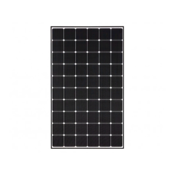
Summary of Contents for LG LG N1C-V5 Series
- Page 1 Installation manual PV Solar MODULE Please read this manual carefully before operating your set and retain it for future reference. N-TYPE MODELS LGXXXN1C(W)-V5 LGXXXN1K-V5 LGXXXN2W-V5 www.lg-solar.com MFL70700902...
-
Page 2: Table Of Contents
TABLE OF CONTENTS SAFETY ..............03 BEFORE & AFTER INSTALLATION ......05 Before Installation ................05 After Installation ...................05 ELECTRICAL INSTALLATION .......06 Danger ....................06 Electrical Connections .................06 Diodes ....................06 Series Connection ................06 Parallel Connection ................07 General Wiring..................07 Earth Grounding ..................07 MECHANICAL INSTALLATION ......08 Module Mounting .................08 Site Consideration ................08 Mounting Methods ................08... -
Page 3: Safety
SAFETY The instructions related to the safety indicated in the Do not approach the damaged following are for preventing unexpected danger or or broken module unless you are damage in advance by safely and exactly using the product. an authorized or qualified expert. Failure to comply may result in DANGER serious bodily injury or death. - Page 4 Do not touch the glass surface or Module frame of the solar module after Module Installing structure installation of the module. It may (Stralght type) Installing structure (bent type) result in injury or death. Heavy objects must be kept off of the solar module.
-
Page 5: Before & After Installation
BEFORE & AFTER INSTALLATION Before Installation Please carefully read this manual before installation. • Partial shadowing may substantially reduce panel and system output and may be the reason for the damage • Solar module installation and maintenance must be of solar module. performed by qualified and authorized installer. -
Page 6: Electrical Installation
Diodes properties or physical configurations in the same system. • All LG modules are equipped with factory installed • Match the polarities of cables and terminals when bypass diodes. The factory-installed diodes provide making the connections; failure to do so may result in proper circuit protection for the module from damage to the panel. -
Page 7: Parallel Connection
LG meet the conditions of safety class II. The national directives must be respected. Module frame Bolt …………... -
Page 8: Mechanical Installation
General Information Excluded Operating Environments • Select the appropriate orientation to maximize sunlight • The solar modules from LG Electronics can not be exposure. operated in a location where they could come in direct • Module should not be mounted or stored in a way that contact with salt water or ammonia. - Page 9 • The solar module may be mounted by using the Mounting by using clamps following methods: (*Torque:8~12N∙m) • The module may be fastened to a support by using • When installing modules in heavy snow areas, clamps on both the long edge and the short edge of it is recommended to be taken an appropriate the modules.
-
Page 10: Disclaimer Of Liability / Disposal
Disclaimer of Liability • By beginning to installation process, the installer has to read and completely understand this Installation Manual. • If installer had any questions regarding this installation manual, the installer would have contacted LG with any questions or concerns. -
Page 11: Product Specifications
10.41 33.3 9.77 1000 1686 1016 17.1 MC4/05-8-cm LG330N1C(W)-V5 0~3% 40.9 10.45 33.7 9.80 1000 1686 1016 17.1 MC4/05-8-cm LG 33N1C(W)-V5 0~3% 40.9 10.47 33.9 9.83 1000 1686 1016 17.1 MC4/05-8-cm 35N1C(W)-V5 0~3% 41.0 10.49 34.1 9.83 1000 1686 1016 17.1... - Page 12 PRODUCT SPECIFICATIONS ◇ Female and male cable couplers ◇ Female cable coupler Model Cable Cross Section Ø A (Cable outer diameter) Rated current 4mm² 5.5 ~ 9mm 12AWG Male cable coupler 4mm² 05-8-cm 5.4 ~ 7.2mm 12AWG http://www.renhesolar.com/ ※ See more information >> http://www.multi-contact.com/ Electrical Properties(NMOT*) Model...
-
Page 13: Dimensions Of Modules
Dimensions of Modules Unit: mm / in. 60Cell Module 72Cell Module... -
Page 14: Appendix
Front : 5400Pa C : 120mm 6point(①+②) B : 843 ±100mm Rear : 1800Pa Rear : 4000Pa Note) All mechanical installation methods(Fig.1 to Fig.6) and bolting method in this appendix were not tested by VDE. It is evaluated by LG internal test. - Page 15 C : 120mm 6point(①+②) B : 10 2 1 ±100mm Rear : 1600Pa Rear : 3000Pa Note) All mechanical installation methods(Fig.1 to Fig.7) and bolting method in this appendix were not tested by VDE. It is evaluated by LG internal test.
-
Page 16: Bolting & Clamp Information
• Follow the clamp manufacturer’s recommended applied torque to fasten the clamps. • Width Height Depth <Edge Clamp> Note) All mechanical installation methods(Fig.1 to Fig.7) and bolting method in this appendix were not tested by VDE. It is evaluated by LG internal test. -
Page 17: Unloading Flow Guide
Unloading Flow Guide If you are unloading using heavy equipment such as a crane, please follow the procedure below. [ Step 1 ] [ Step 2 ] [ Step 3 ] [ Step 4 ] Step 1. Place the packaging on a flat surface. Step 2. - Page 18 Seoul 07336, Korea Contact: solarinfo@lge.com http://www.lg-solar.com This document is subject to change without notice. LG, LG logo and Life's Good are trademarks of LG Electronics, Inc. worldwide. Trademarks and intellectual properties of LG Electronics, Inc. are protected by international copyright laws.


