Table of Contents
Advertisement
Quick Links
Advertisement
Table of Contents

Summary of Contents for Makita DBN900
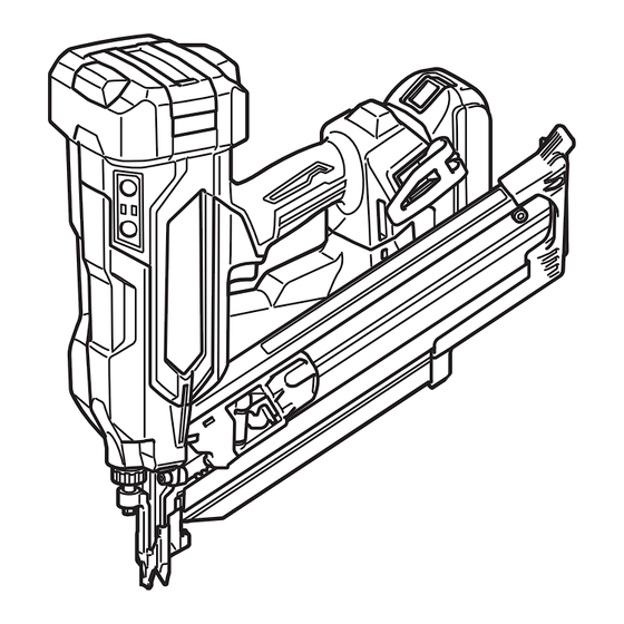
- Page 1 INSTRUCTION MANUAL Cordless Framing Nailer DBN900 DBN901 Read before use.
-
Page 2: Specifications
SPECIFICATIONS Model: DBN900 DBN901 Figure of nail head Clipped Round Nail length 50 mm - 90 mm Shank diameter ø2.9 mm - ø3.3 mm ø2.9 mm - ø3.8 mm Magazine capacity 51 - 61 nails (1 strip + 11 - 21 nails) -
Page 3: Declarations Of Conformity
Sound power level (L ) : *** dB (A) you to lose control. Uncertainty (K) : *** dB (A) Electrical safety Power tool plugs must match the outlet. Never WARNING: Wear ear protection. modify the plug in any way. Do not use any adapter plugs with earthed (grounded) power Vibration tools. - Page 4 these are connected and properly used. Use of taking into account the working conditions dust collection can reduce dust-related hazards. and the work to be performed. Use of the power Do not let familiarity gained from frequent use could result in a hazardous situation. of tools allow you to become complacent and ignore tool safety principles.
- Page 5 workpiece to depress the contact element. Do not actuate the tool unless the tool is If the tool Never defeat its purpose by securing the con- is not in contact with the workpiece, the fastener tact element back or by depressing it by hand. 21.
-
Page 6: Functional Description
Use of non-genuine Makita batteries, or batteries that have been altered, may result in the battery bursting Fig.1 also void the Makita warranty for the Makita tool and 1. Red indicator 2. Button 3. Battery cartridge charger. Tips for maintaining maximum... -
Page 7: Overheat Protection
Makita Service Center. Indicating the remaining battery capacity Only for battery cartridges with the indicator Press the check button on the battery cartridge to indi- cate the remaining battery capacity. The indicator lamps light up for a few seconds. -
Page 8: Adjusting The Nailing Depth
NOTE: The switch design varies depending on your region of residence. Fig.5 1. Actuation mode switch button 2. Sequential actu- ation mode lamp 3. Contact actuation mode lamp Fig.4 1. Main power button 2. Power indicator Mode Actuation Feature switch mode NOTE: The tool cannot be turned on while either the Full sequen-... - Page 9 NOTE: of the lamp. Be careful not to scratch the lens of the lamp, or it may lower the illumination. NOTE: The tool may not drive nails after the battery becomes low on power even while the lamp remains lit. In this case, charge the battery cartridge. ASSEMBLY CAUTION: Always make sure that your...
- Page 10 Fig.9 Fig.11 1. Slit 2. Nail head outline 1. Pusher lever 2. Nail pusher Pinch the pusher lever to raise the pusher plate up above the nail strip loaded. Then pull the nail pusher NOTICE: Make sure that the nail strip is properly towards the slit.
- Page 11 Fig.15 1. Standard equipped magazine Insert the lock plate in the extended capacity magazine into the lock groove in the driver guide at an angle. Align the bolt holes in the magazine with those in the driver guide. Then tighten the bolts a little at a time using the hex wrench.
- Page 12 NOTE: Make sure that the hooked arm ends of the nose adapter fully engage the contact top. Fig.19 1. Hooked arm ends Detaching nose adapter Turn the tool upside down. Disengage the arms of the nose adapter from the contact top and slide the nose adapter out a bit to make a gap between their outlines.
-
Page 13: Operation
The C-shaped hook can be positioned open at 90-degree intervals. Push and hold the hook upwards and swing it to your desired position. Fig.21 Clip-shaped hook Insert the clip-shaped hook into a groove in the tool housing, and then secure it with a hex bolt. Fig.24 To remove the clip-shaped hook, loosen the bolt and 1. -
Page 14: Full Sequential Actuation
If the tool works in case step 3 or 4 described above, safety system is not functioning properly. Stop using the tool immediately and ask your local Makita Service Fig.27 Center. 1. Actuation mode switch button 2. Sequential... - Page 15 Press and hold the main power button to turn on the tool. Press and shortly hold the actuation mode switch button to select the contact actuation mode. The contact actuation mode lamp lights up. Pull the switch trigger. Fig.29 1. Switch trigger lift the contact element up from the material.
-
Page 16: Removing Jammed Nails
CAUTION: To address frequent jamming or hard-to-clear jamming situations, consult your local Makita Service Center. Remove the battery cartridge from the tool. Take out all the nails left in the magazine. NOTE: ming occurs inside the nail feeding and driving unit. -
Page 17: Preventive Maintenance
To maintain product SAFETY and RELIABILITY, Fig.36 1. Nail driver 2. Contact top be performed by Makita Authorized or Factory Service Centers, always using Makita replacement parts. Preventive maintenance that the contact element functions properly. Thoroughly clean and inspect moving components (i.e., contact element, nail pusher, etc.) on a regular basis,... -
Page 18: Optional Accessories
OPTIONAL ACCESSORIES CAUTION: These accessories or attachments are recommended for use with your Makita tool The use of any other accessories or attachments might present a risk of for its stated purpose. If you need any assistance for more details regard- ing these accessories, ask your local Makita Service Center. - Page 20 885A75-220 20240228...


