Sign In
Upload
Manuals
Brands
ABB Manuals
Inverter
PVS800-57-0100kW-A
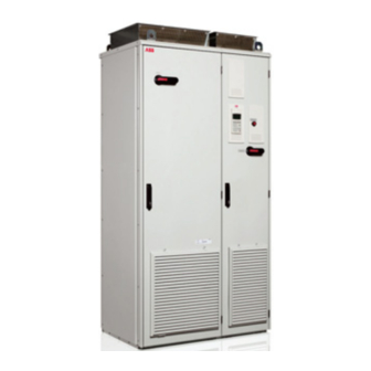
ABB PVS800-57-0100kW-A Central Inverter Manuals
Manuals and User Guides for ABB PVS800-57-0100kW-A Central Inverter. We have
1
ABB PVS800-57-0100kW-A Central Inverter manual available for free PDF download: Hardware Manual
ABB PVS800-57-0100kW-A Hardware Manual (180 pages)
PVS800-57 series central inverters
Brand:
ABB
| Category:
Inverter
| Size: 10.24 MB
Table of Contents
List of Related Manuals
2
Table of Contents
7
1 Safety Instructions
13
Contents of this Chapter
13
Use of Warnings
13
Safety in Installation and Maintenance
14
Precautions before Electrical Work
14
Electrical Safety
16
Grounding
17
General Safety
18
Printed Circuit Boards
20
Fiber Optic Cables
20
Start-Up and Operation
21
2 Introduction to the Manual
23
Contents of this Chapter
23
Target Audience
23
Contents of the Manual
23
Related Documents
24
Categorization by Frame Size and Option Code
24
Quick Installation, Commissioning and Operation Flowchart
24
Terms and Abbreviations
25
3 Operation Principle and Hardware Description
27
Contents of this Chapter
27
Product Overview
28
Block Diagram of Solar Generator System
29
Example Main Circuit Diagram of the Inverter System (R8I)
33
Example Main Circuit Diagram of the Inverter System (2 × R8I)
36
External 100 V AC, 115 V AC or 200 V AC Auxiliary Power Supply (Options +G396, +G397 and +G398)
37
Auxiliary Power Supply from the Inverter Main Circuit (Option +G415)
37
Descriptions of Symbols
38
Example Main Circuit Diagram of the Inverter System (3 × R8I)
40
External 100 V AC, 115 V AC or 200 V AC Auxiliary Power Supply (Options +G396, +G397 and +G398)
41
Auxiliary Power Supply from the Inverter Main Circuit (Option +G415)
41
Descriptions of Symbols
42
Electrical Power Network Supervision Functions
43
Positive or Negative Pole Grounding (Options +F282 and +F283)
44
Reduced Run Operation in Case of a Hardware Failure
44
Layout Drawings
45
Cabinet Layout of Frame R7I
46
Cabinet Layout of Frame R8I
47
Cabinet Layout of Frame 2 × R8I
48
Cabinet Layout of Frame 3 × R8I
50
Door Devices
51
Inverter Module (R7I)
52
Inverter Module (R8I)
52
Connections and Interfaces Overview
54
Connection Examples
56
CDP-312R Control Panel
57
Type Designation Labels
58
Inverter Label
58
Inverter Module Label
59
Type Designation Key
60
Types -0100Kw-A to -0315Kw-B
60
Types -0500Kw-A to -1000Kw-C
62
4 Mechanical Installation
65
Contents of this Chapter
65
Checking the Installation Site
65
Required Tools
66
Checking the Delivery
66
Moving the Unit
67
Placing the Unit
68
Overview of the Installation Process
68
Fastening the Cabinet to the Floor
69
Alternative 1 - Clamping
69
Alternative 2 - Using the Holes Inside the Cabinet
70
Miscellaneous
71
Preventing the Recirculation of Hot Air
71
Ventilation Duct at the Air Outlet of the Cabinet
71
Calculating the Required Static Pressure Difference
72
Cable Duct in the Floor below the Cabinet
73
5 Planning the Electrical Installation
75
Contents of this Chapter
75
Limitation of Liability
75
Selecting the Transformer
75
Requirements for the Transformer
76
Selecting the Grid Disconnecting Device
77
Selecting the DC Input Disconnecting Device
77
Checking the Compatibility of the Solar Generator and Inverter
77
Selecting the Power Cables
77
General Rules
77
Recommended AC Output Power Cable Types
79
Not Allowed Power Cable Types
79
Selecting the Control Cables
79
General Rules
79
Signals in Separate Cables
80
Signals Allowed to be Run in the same Cable
80
Relay Cable Type
80
Installation Sites above 2000 Metres (6560 Feet)
80
Routing the Cables
80
Separate Control Cable Ducts
81
Implementing Short-Circuit and Thermal Overload Protection
81
Protecting the Inverter and AC Output Cable in Short-Circuit Situations
81
Protecting the Photovoltaic Generator and DC Input Cable in Short-Circuit Situations
81
Protecting the Inverter and the AC Output Cable against Thermal Overload
81
Supplying Power for the Auxiliary Circuits
82
Implementing the Low Voltage Ride-Through Function
82
Supplying Circuits from the AC Output of the Inverter
82
Implementing Ground Fault Monitoring in IT (Ungrounded) Systems
83
Insulation Monitoring Device (Options +Q954, +Q976 and +Q981)
83
Safety Information
83
Customer Wiring
84
Start-Up
84
More Information
84
Implementing Positive or Negative Pole Grounding (Options +F282 and +F283)
84
Limiting the Conducted Disturbances with the EMC Filter (Option +E216) in Low-Voltage TN (Grounded) Networks
84
Instructions for Inverters Delivered Without Input DC Fuses (Option +0F291)
84
Mechanical Installation of the Input DC Fuses
84
6 Electrical Installation
85
Contents of this Chapter
85
Warnings
85
Checking the Insulation of the Assembly
85
Inverter
85
AC Output Cable
85
DC Input Cable(S)
85
Photovoltaic Generator
86
Checking the Compatibility with IT (Ungrounded) Systems
86
Connecting the Power Cables
86
Connection Diagram of a Shielded Cable
86
Connection Diagram of a Four-Conductor System
87
DC Input Cable Connection Procedure
88
AC Output Cable Connection Procedure
89
Connecting the External Power Supply Cable for the Auxiliary Circuit
91
Checking the Wiring of the Auxiliary Voltage Transformer
91
And +G415)
91
Connecting the DC Current Measurement Signals to an External Controller
92
G416)
92
Connecting the Junction Box Power Supply (Option +G410)
93
Connecting the EMC Filter (Option +E216)
93
Connecting the Control Cables
93
Default I/O Connection Diagram (RDCU - A43)
94
Default I/O Connection Diagram (RDCU - A41)
95
Default I/O Connections (RDIO on RDCU - A41)
96
Connection Procedure
97
Making 360 Degrees Grounding at the Cabinet Lead-Through for the Control Cables
97
Connecting the Cables to the I/O Terminals
98
Connecting a PC
98
Installing Optional Modules
98
Mechanical Installation
98
Wiring the Modules
98
7 Installation Checklist
99
Contents of this Chapter
99
Checklist
99
8 Start-Up
101
Contents of this Chapter
101
Start-Up Procedure
101
Safety
101
Primary and Ambient Condition Checks
101
Setting up the Insulation Monitoring Device
102
And +Q981)
102
SETTING up CURRENT TRANSDUCERS (Option +G417) for ALL DC INPUTS
102
Adjusting Grounding Resistance for Positive or Negative Pole
103
GROUNDING (Options +F282 and +F283)
103
Parameter Settings before First Start
103
FIRST START (Local Control Mode)
103
SETTING up FIELDBUS CONTROL (Option +K454, +K458, +K466, or +K467)
105
Registering the Inverter
105
Connecting Drivewindow
106
Configuring the NETA-01 Ethernet Adapter Module
106
Configuring the NETA-21 Remote Monitoring Tool
106
9 Fault Tracing
107
Contents of this Chapter
107
Leds
107
Warning and Fault Messages Displayed by the CDP-312R Control Panel
108
Fault: same ID Numbers
108
Fault Tracing of the Insulation Monitoring Device (Options +Q954, +Q976 and +Q981)
108
10 Maintenance
109
Contents of this Chapter
109
Maintenance Intervals
109
Descriptions of Symbols
109
Recommended Annual Maintenance Actions by the User
110
Recommended Maintenance Intervals after Start-Up
110
Cleaning the Interior of the Cabinet
111
Replacing the Air Filters
111
Inlet (Door) Filters
111
Cleaning the Heatsink
112
Checking and Cleaning the Power Connections (R8I, 2 × R8I, 3 × R8I)
113
Fans
114
Replacing the LCL Filter Cooling Fan (R7I)
114
Replacing the LCL Filter Cooling Fan (R8I, 2 × R8I, 3 × R8I)
115
Replacing the Door Fans
116
Replacing the Cabinet Roof Fans (R8I)
117
Replacing the Cooling Fan of the Inverter Module (R7I)
118
Replacing the Cooling Fan of the Inverter Module (R8I, 2 × R8I, 3 × R8I)
119
Replacing the Inverter Module (Frames R8I, 2 × R8I, 3 × R8I)
120
Extracting the Module from the Cubicle
120
Inserting the Module into the Cubicle
122
Replacing the LCL Filter
122
Capacitors
123
Reforming the Capacitors
123
11 Technical Data
125
Contents of this Chapter
125
Ratings
125
Altitude Derating
126
Temperature Rating Curves
126
Temperature Rating of Types -0100Kw-A and -0250Kw-A
126
Temperature Rating of Types -0315Kw-B and -0630Kw-B
127
Temperature Rating of Types-0500Kw-A, -0875Kw-B and -1000Kw-C
128
With Temperature Compensated Altitude Derating
128
Type Equivalence Table
129
Fuses
129
Main Circuit AC Fuses
129
Inverter DC Fuses
130
DC Fuses for 2 DC Input Connections (Option +2H382)
130
DC Fuses for 4 DC Input Connections (Option +4H382)
130
DC Fuses for 5 DC Input Connections (Option +5H382)
130
DC Fuses for 8 DC Input Connections (Option +8H382)
130
DC Fuses for 10 DC Input Connections (Option +10H382)
131
DC Fuses for 12 DC Input Connections (Option +12H382)
131
DC Fuses for 15 DC Input Connections (Option +15H382)
131
DC Fuses for 16 DC Input Connections (Option +16H382)
131
DC Fuses for 20 DC Input Connections (Option +20H382)
131
Fuses for Inverters Delivered Without Input DC Fuses (Option +0F291)
132
Miniature DC Circuit Breakers (Option +H377)
133
Miniature Circuit Breakers for Options +G300 and +G410
133
Dimensions, Weights and Free Space Requirements
134
Losses, Cooling Data and Noise
135
Terminal and Lead-Through Data for the DC Input Power Cable
135
Terminal and Lead-Through Data for the AC Output Power Cable
137
AC Output Connection Specification
138
DC Input Connection Data
139
Control Unit (RDCU/RMIO) Connection Data
140
Analog Inputs
140
Constant Voltage Output
140
Auxiliary Power Output
140
Analog Outputs
140
Digital Inputs
140
Auxiliary Power Connection Data
140
Relay Outputs
141
DDCS Fiber Optic Link
141
24 V DC Power Input
141
Isolation and Grounding Diagram
142
Efficiency
143
Degrees of Protection
145
Protective Class
145
Ambient Conditions
146
Materials
147
Auxiliary Circuit Power Consumption
148
Applicable Standards and Requirements
149
CE Marking
149
Compliance with the European Low Voltage Directive
149
Compliance with the European EMC Directive
149
Compliance with EMC Standards en 61000-6-2:2005 and en 61000-6-4:2007
149
Medium Voltage Network
150
Low-Voltage Network
150
C-Tick" Marking
150
12 Dimension Drawings
151
Contents of this Chapter
151
Frame R7I
152
Frame R8I
155
Frame 2 × R8I
162
Frame 3 × R8I
170
Further Information
179
Advertisement
Advertisement
Related Products
ABB PVS800-57-0875kW-B
ABB PVS800-57-1000kW-C
ABB PVS800-57-0250kW-A
ABB PVS800-57-0315kW-B
ABB PVS800-57-0500kW-A
ABB PVS800-57-0630kW-B
ABB PVS800-57B
ABB PVS800-IS
ABB PVS-60-TL-S-R-US
ABB PVS-100 Series
ABB Categories
Industrial Equipment
Controller
Measuring Instruments
Battery Charger
DC Drives
More ABB Manuals
Login
Sign In
OR
Sign in with Facebook
Sign in with Google
Upload manual
Upload from disk
Upload from URL