Sign In
Upload
Manuals
Brands
LG Manuals
Air Conditioner
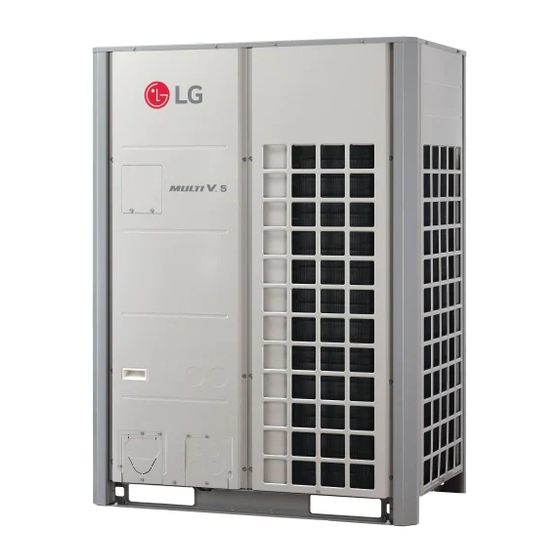
Multi V 5
User Manuals: LG Multi V 5 VRF HVAC System
Manuals and User Guides for LG Multi V 5 VRF HVAC System. We have
6
LG Multi V 5 VRF HVAC System manuals available for free PDF download: Service Manual, Data Manual, Manual Book, Engineering Manual, Installation Manual, Reference Manual
LG Multi V 5 Service Manual (236 pages)
Brand:
LG
| Category:
Air Conditioner
| Size: 13.52 MB
Table of Contents
Table of Contents
3
Safety Precautions
4
Table of Symbols
4
Installation
4
Wiring
6
Operation
7
Safety Precautions
7
Heat Recovery Units (HRU)
8
Outdoor Units (ODU)
8
Unit Nomenclature
8
Outdoor Wiring Diagram
9
Wiring Diagrams
9
Wiring Diagrams
16
Heat Pump – Cooling Mode
17
Refrigerant Flow Diagrams
17
Heat Pump – Heating Mode
18
Heat Pump – Oil Return and Defrost Operation
19
Heat Pump – Lower HEX Defrost Operation
20
Heat Pump – Upper HEX Defrost Operation
21
Heat Recovery – Cooling Mode
27
Heat Recovery – Heating Mode
28
Heat Recovery – Cooling-Based Simultaneous Operation
29
Heat Recovery – Heating-Based Simultaneous Operation
30
Heat Recovery – Balanced Simultaneous Operation
31
Heat Recovery – Oil Return and Defrost Operation
32
Heat Recovery – Lower HEX Defrost Operation
33
Heat Recovery – Upper HEX Defrost Operation
34
Refrigerant Flow Diagrams
42
Basic Control
43
Compressor Control
43
Normal Operation
43
Outdoor Unit Functions
43
Avoiding Excessively High Discharge Temperatures
44
Main EEV Control
44
Master and Slave Outdoor Unit EEV Control
44
Subcooling EEV Control
44
Oil Return Control
45
Oil Return Control in Heating Mode
45
Oil Return in Cooling Mode
45
Special Control
45
Defrost Control
46
Defrost Control Stop Operation
46
Partial Defrost
46
Partial Defrost Control Stop Operation
46
Oil Equalizing Control
47
Special Control
47
Stop Operation Control
47
Stop Operation Control in Heating Mode
47
Pressure Control in Heating Mode
48
Pressure Protection Control
48
Discharge Temperature/Inverter Protection
49
Inverter Compressor Protection Control
49
Initial Setup
50
Other Controls
50
Auto Addressing Flowchart
52
Other Controls
53
Quick Control Setting
53
Troubleshooting a Failed Indoor Unit Auto Addressing Procedure
53
Setting the Optional Modes
54
Automatic Emergency Operation (Automatic Backup Function)
56
Emergency Operation
56
Manual Emergency Operation (Manual Backup Function)
56
Fault Detection Diagnosis (FDD) Checklist
57
Fault Detection Diagnosis (FDD) Codes
57
Refrigerant Auto Charge (Fd1 [Cooling], Fd2 [Heating])
58
Refrigerant Charge Procedure
59
Refrigerant Auto Judge (Fd3 [Cooling], Fd4 [Heating])
60
Integrated Test Run (ITR) (Fd7)
61
Cool/Heat Selector
64
Static Pressure Compensation Function (Fn2)
65
Night Low Sound Function (Fn3)
66
(Overall) Defrost Function (Fn4)
67
Outdoor Unit Addressing Function
67
Rapid Defrost
68
Snow Removal Assist/Rapid Defrost Function
68
Adjusting Indoor Unit Capacity (Fn7)
69
Adjusting Target Pressure (Fn8)
69
High Efficiency Function (Cooling Operation) (Fn10)
70
Low Ambient Kit Function (Fn9)
70
High Efficiency Function Operation (Auto Dust Throw Mode) (Fn11)
71
Smart Load Control (SLC) Function
72
Humidity Reference (Fn16)
73
Power Consumption Display (Fn21)
73
Drain Pan Heater (Optional) Function (Fn23)
74
Overall Defrost Operating in Low Temperatures (Heating) (Fn22)
74
Comfort Cooling (Id10)
75
Pump down (SE1, Pd)
76
Pump out (SE2, Po)
77
Pump out for Heat Recovery Systems
78
Pump out for Heat Pump Systems
79
Vacuum Mode (SE3, Vacc)
80
Forced Oil Return (SE5, 01)
81
Manual Back up for Inverter Compressor (SE4)
81
Forced Defrost (SE6, Def)
82
Cycle Data View (SE8)
83
Refrigerant Sound Reduction Mode
84
Fan Low Sound in Heating (SE11)
85
Number of Partial Defrosts (SE12)
85
Level Change of Error Code CH200 (SE14)
86
Auto Back up for Inverter Compressor
87
Setting Optional Modes
87
Heat Recovery Unit Parts Diagram
88
Heat Recovery Units Parts Functions
88
Dimensional Diagrams
89
PRHR022A Heat Recovery Unit
89
PRHR032A Heat Recovery Unit
90
Dimensional Diagrams
91
PRHR042A Heat Recovery Unit
91
Wiring Diagram
92
Refrigerant Circuit Diagram
93
Functions
94
Valve Control
94
Heat Recovery Units
95
Liquid Bypass Control
95
Oil Return/Defrost Control
95
Setting Outdoor Units in Dual/Triple Frame Systems
96
Setting Outdoor Units to Heat Pump or Heat Recovery System
96
PCB Settings
96
Outdoor Unit DIP Switch Settings
96
Heat Recovery Unit Settings
97
Addressing with Heat Recovery Units
97
Main Function of SW02M
98
Due to Our Policy of Continuous Product Innovation, some Specifications May Change Without Notification
98
Due to Our Policy of Continuous Product Innovation, some Specifications May Change Without Notification
99
Due to Our Policy of Continuous Product Innovation, some Specifications May Change Without Notification
100
SW05M Function (Rotary Switch for Addressing Heat Recovery Units)
101
Due to Our Policy of Continuous Product Innovation, some Specifications May Change Without Notification
101
Heat Recovery Unit Settings
102
Indoor Unit Auto Addressing Procedure
103
Indoor Unit Addressing
104
Auto Addressing for Pipe Detection
105
Pipe Detection Addressing
106
Due to Our Policy of Continuous Product Innovation, some Specifications May Change Without Notification
106
Manual Addressing for Pipe Detection
107
Due to Our Policy of Continuous Product Innovation, some Specifications May Change Without Notification
107
Manual Addressing for Pipe Detection Example (Non-Zone Setting)
108
Due to Our Policy of Continuous Product Innovation, some Specifications May Change Without Notification
108
Manual Addressing for Pipe Detection Example (Zone Setting)
109
Due to Our Policy of Continuous Product Innovation, some Specifications May Change Without Notification
109
Example of Checking the Valve Address
110
Identifying the Manual Valve Address
110
Pipe Detection Addressing
110
Test Run Checklist
111
Troubleshooting Main Components
111
Main Component Errors
112
Self Diagnostics Check
113
Run Self Diagnostics Check
113
Checking the Compressor
114
Checking the Outdoor Unit Fan Motor
115
Checking the Electronic Expansion Valves
116
Checking the Electronic Expansion Valves
118
Checking the Phase Diode Bridge
119
Checking the Inverter Compressor Phase Diode Bridge
119
Checking the Inverter Insulated-Gate Bipolar Transistor
120
Checking Intelligent Power Module (IPM)
120
Checking the Fan Intelligent Power Module (IPM)
121
Sensors and Outdoor Fan
122
Checking the High / Low Pressure Sensors
122
Checking the Outdoor Fan
122
Checking the Valves
123
Oil Return Solenoid Valve
123
Partial Defrost Solenoid Valve
123
Supercooled Bypass Valve
123
Checking the Four-Way Reverse Valve
124
Checking the Temperature Sensors
124
Error Code General Information
125
Error Code Tables
126
Error Code Display
126
Nomenclature Definitions
126
Error Nos. 01, 02, 06, and 17
136
Error No. 03
137
Error Codes
137
Error No. 04
138
Error No. 05
140
Error No. 09
141
Error No. 10
142
Dismantling/Servicing the Control Box and Inverter PCB
143
Error No. 21
144
Error No. 22
146
Error No. 23
148
Error No. 24
149
Error No. 25
150
Error No. 26
151
Error No. 29
153
Error Nos. 32 and 33
155
Error No. 34
156
Error No. 35
157
Error No. 36
158
Error No. 40
159
Error Nos. 41 and 47
160
Error Nos. 42 and 43
161
Error Nos. 44, 45, 46, 49, 153, and 154
162
Error No. 50
163
Error No. 51(1)
164
Error No. 51(2) (for Heat Recovery Systems Only)
165
Error No. 52
166
Error No. 53
168
Error No. 57
170
Error No. 60
171
Error No. 62
172
Error No. 65
173
Error No. 67
174
Error No. 75
176
Error No. 77
177
Error No. 79
178
Error No. 86
180
Error No. 87
181
Error No. 104
182
Error No. 105
185
Error No. 106
187
Error No. 107
189
Error Nos. 113, 114, and 115
190
Error No. 145
191
Error No. 150
192
Error No. 151
193
Error No. 182
196
Error No. 187
197
Error No. 193
198
Error No. 194
199
Error No. 2001
201
Error Nos. 201C, 202C, 203C
202
Error No. 204 C
203
Error No. 205 C
204
Error No. 206 C
205
Error No. 237
206
Error No. 238
207
Error No. 242
208
Replacing the Inverter PCB Heat Sink
209
Checking Input Voltage in Case of Power on
210
Checking Main PCB DC Voltage in Case of Power on
211
Checking Converter DC Link Voltage in Case of Compressor Operating
212
Case of Power on
213
Checking Inverter PCB in Case of Power off
214
Power System Wiring Diagram
215
PCB Locations
216
Outdoor Unit Parts
217
Main PCB
217
Pcbs
217
External PCB
218
Inverter PCB for 208-230V Outdoor Units (17Kw)
219
Inverter PCB for 208-230V Outdoor Units (12Kw)
220
Inverter PCB for 460V Outdoor Units (17Kw)
221
Inverter PCB for 460V Outdoor Units (12Kw)
222
Fan PCB
223
Noise Filter PCB for 208-230V Outdoor Units (17Kw)
224
Noise Filter PCB for 208-230V Outdoor Units (12Kw)
224
Noise Filter PCB for 460V Outdoor Units (17Kw)
225
Noise Filter PCB for 460V Outdoor Units (12Kw)
225
Pcbs - Expanded Internal View
226
Expanded Frame View for 6-Ton (Small Frame) Outdoor Units
229
Expanded Frame View for 8- and 10-Ton (Large Frame) Outdoor Units
230
Expanded Frame View for 12- to 20-Ton (Large Frame) Outdoor Units
231
Expanded Piping View
232
Expanded Piping View for 8- and 10-Ton (Large Frame) Outdoor Units
233
Expanded Piping View for 12- to 20-Ton (Large Frame) Outdoor Units
234
Parts
234
Advertisement
LG Multi V 5 Data Manual (162 pages)
Brand:
LG
| Category:
Air Conditioner
| Size: 1.37 MB
Table of Contents
Table of Contents
3
Table of Symbols
3
Performance Data
4
72,000 Btu/H 208-230V / 460V Outdoor Units
5
Arum072Bte5 / Arum072Dte5
5
96,000 Btu/H 208-230V / 460V Outdoor Units
10
Arum096Bte5 / Arum096Dte5
10
120,000 Btu/H 208-230V / 460V Outdoor Units
15
Arum121Bte5 / Arum121Dte5
15
144,000 Btu/H 208-230V / 460V Outdoor Units
20
Arum144Bte5 / Arum144Dte5
20
168,000 Btu/H 208-230V / 460V Outdoor Units
25
Arum168Bte5 / Arum168Dte5
25
192,000 Btu/H 208-230V / 460V Outdoor Units
30
Arum192Bte5 / Arum192Dte5
30
216,000 Btu/H 208-230V / 460V Outdoor Units
35
Arum216Bte5 / Arum216Dte5
35
240,000 Btu/H 208-230V / 460V Outdoor Units
40
Arum241Bte5 / Arum241Dte5
40
264,000 Btu/H 208-230V / 460V Outdoor Units
45
Arum264Bte5 / Arum264Dte5
45
288,000 Btu/H 208-230V / 460V Outdoor Units
50
Arum288Bte5 / Arum288Dte5
50
312,000 Btu/H 208-230V / 460V Outdoor Units
55
Arum312Bte5 / Arum312Dte5
55
336,000 Btu/H 208-230V / 460V Outdoor Units
60
Arum336Bte5 / Arum336Dte5
60
360,000 Btu/H 208-230V / 460V Outdoor Units
65
Arum360Bte5 / Arum360Dte5
65
384,000 Btu/H 208-230V / 460V Outdoor Units
70
Arum384Bte5 / Arum384Dte5
70
408,000 Btu/H 208-230V / 460V Outdoor Units
75
Arum408Bte5 / Arum408Dte5
75
432,000 Btu/H 208-230V / 460V Outdoor Units
80
Arum432Bte5 / Arum432Dte5
80
456,000 Btu/H 208-230V / 460V Outdoor Units
85
Arum456Bte5 / Arum456Dte5
85
480,000 Btu/H 208-230V / 460V Outdoor Units
90
Arum480Bte5 / Arum480Dte5
90
504,000 Btu/H 208-230V / 460V Outdoor Units
95
Arum504Bte5 / Arum504Dte5
95
72,000 Btu/H 208-230V / 460V Outdoor Units (Heating Capcity)
100
ARUM072BTE5 / ARUM072DTE5 (Heating Capacity)
100
Heating Capacity Data
100
96,000 Btu/H 208-230V / 460V Outdoor Units (Heating Capacity)
103
ARUM096BTE5 / ARUM096DTE5 (Heating Capacity)
103
120,000 Btu/H 208-230V / 460V Outdoor Units (Heating Capacity)
106
ARUM121BTE5 / ARUM121DTE5 (Heating Capacity)
106
144,000 Btu/H 208-230V / 460V Outdoor Units (Heating Capacity)
109
ARUM144BTE5 / ARUM144DTE5 (Heating Capacity)
109
168,000 Btu/H 208-230V / 460V Outdoor Units (Heating Capacity)
112
ARUM168BTE5 / ARUM168DTE5 (Heating Capacity)
112
192,000 Btu/H 208-230V / 460V Outdoor Units (Heating Capacity)
115
ARUM192BTE5 / ARUM192DTE5 (Heating Capacity)
115
216,000 Btu/H 208-230V / 460V Outdoor Units (Heating Capacity)
118
ARUM216BTE5 / ARUM216DTE5 (Heating Capacity)
118
240,000 Btu/H 208-230V / 460V Outdoor Units (Heating Capacity)
121
ARUM241BTE5 / ARUM241DTE5 (Heating Capacity)
121
264,000 Btu/H 208-230V / 460V Outdoor Units (Heating Capacity)
124
ARUM264BTE5 / ARUM264DTE5 (Heating Capacity)
124
288,000 Btu/H 208-230V / 460V Outdoor Units (Heating Capacity)
127
ARUM288BTE5 / ARUM288DTE5 (Heating Capacity)
127
312,000 Btu/H 208-230V / 460V Outdoor Units (Heating Capacity)
130
ARUM312BTE5 / ARUM312DTE5 (Heating Capacity)
130
336,000 Btu/H 208-230V / 460V Outdoor Units (Heating Capacity)
133
ARUM336BTE5 / ARUM336DTE5 (Heating Capacity)
133
360,000 Btu/H 208-230V / 460V Outdoor Units (Heating Capacity)
136
ARUM360BTE5 / ARUM360DTE5 (Heating Capacity)
136
384,000 Btu/H 208-230V / 460V Outdoor Units (Heating Capacity)
139
ARUM384BTE5 / ARUM384DTE5 (Heating Capacity)
139
408,000 Btu/H 208-230V / 460V Outdoor Units (Heating Capacity)
142
ARUM408BTE5 / ARUM408DTE5 (Heating Capacity)
142
432,000 Btu/H 208-230V / 460V Outdoor Units (Heating Capacity)
145
ARUM432BTE5 / ARUM432DTE5 (Heating Capacity)
145
456,000 Btu/H 208-230V / 460V Outdoor Units (Heating Capacity)
148
ARUM456BTE5 / ARUM456DTE5 (Heating Capacity)
148
480,000 Btu/H 208-230V / 460V Outdoor Units (Heating Capacity)
151
ARUM480BTE5 / ARUM480DTE5 (Heating Capacity)
151
504,000 Btu/H 208-230V / 460V Outdoor Units (Heating Capacity)
154
ARUM504BTE5 / ARUM504DTE5 (Heating Capacity)
154
Performance Data
156
Correction Factors
157
Defrost Correction Factor for Heating Operation
158
Equivalent Length Calculation for Correction Factors
158
Pipe Length Correction Factor
158
Elevation Correction Factors
159
Correction Factors
160
LG Multi V 5 Manual Book (133 pages)
Brand:
LG
| Category:
Heat Pump
| Size: 19.38 MB
Table of Contents
Table of Contents
3
Ⅰ. Basic Part
4
Unit Conversion
5
Temperature Vs. Pressure of Ref
5
P-H Diagram_R410A
7
P-H Diagram_R134A
8
Ⅱ. Multi V 5 Introduction
9
Nomenclature
10
Line up / Capacity
11
Piping Diagrams
13
Wiring Diagrams
28
Checking Point
32
Lgmv
33
Lack of Cooling
33
Lack of Heating
34
Check the Amount of Refrigerant
35
Cycle Changes by Amount of Refrigerant
37
Self-Diagnosis Function
38
Error Code Display
39
Error Code Check
41
Compressor
50
Eev
75
Solenoid Valve
75
Way Valve
75
The Phenomena from Main Component Failure
76
Compressor
76
Check Valve (Outdoor EEV Check Valve)
85
Check Valve (Oil Separator)
85
Outdoor Fan & Fan Motor
86
Temperature Sensor
87
Pressure(High/Low) Sensor
87
Humidity Sensor
88
Pressure Switch
89
Main PCB
89
External PCB
90
Inverter PCB
91
Fan PCB
92
Communication PCB
93
Phase Bridge Diode
94
Inverter IGBT
94
Fan IPM
95
Central Controller PC Status
96
App. Service & Replace Method of Control Box, Inverter PCB
98
Ⅳ. Function Control
98
Generation 4 Features
99
Function Control Setting
99
FDD Mode
101
Function Mode
106
FN 4 Overall Defrost
109
FN 9 Low Ambient Kit
112
FN 12 Compressor Max. Frequency Limit
113
Auto Dust Removal Mode
113
The Connecting of Central Control at IDU Terminals
117
FN 21 the Smart Plug
118
Overall Defrost Entrance for Low Temperature
118
SVC Mode
119
Display Cycle Information
124
SE 9 Noise Reduction
125
Heating Fan Low Noise
126
IDU Mode
127
EEV Pulse of Non-Operating IDU in Heating
127
Set IDU Superheat
128
Set IDU Subcool
128
Set Auto Pipe Detection
128
Start Auto Pipe Detection
128
Set Zone Master
129
Operating IDU Low Noise
130
In Cooling IDU EEV Max. Pulse
130
Comfort Cooling
131
Non-Operating IDU Subcool
132
Set IDU Superheat for Fan
132
Advertisement
LG Multi V 5 Engineering Manual (105 pages)
Brand:
LG
| Category:
Fan
| Size: 13.74 MB
Table of Contents
Table of Contents
3
Unit Nomenclature
4
LG Air Conditioner Technical Solution (LATS)
5
Outdoor Unit Product Data
7
Mechanical Specifications
8
Features
9
General Data
10
Electrical Data
20
Connection Limitations
22
Dimensions
23
Wiring Diagrams
27
Refrigerant Flow Diagrams
35
Acoustic Data
61
Accessories
67
Heat Recovery Unit Product Data
74
Mechanical Specifications
75
General Data
76
Electrical Data
76
Dimensions
76
Wiring Diagram
80
Refrigerant Flow Diagram
81
Accessories
82
Electrical Connections
83
System for Heat Pump Operation
84
System for Heat Recovery Operation
85
DIP Switch Settings for Use with Gen 4 Indoor Units
86
Placement Considerations
87
Piping Limitations
88
Refrigerant Piping for Separated Outdoor Units
94
Selecting the Best Location for Outdoor Unit(S)
97
Outdoor Unit Clearance Requirements
99
Installing Outdoor Units Indoors
100
Selecting the Best Location / Clearance Requirements for Heat Recovery Unit(S)
102
LG Multi V 5 Installation Manual (25 pages)
DRAIN PAN HEATER
Brand:
LG
| Category:
Heater
| Size: 10.56 MB
LG Multi V 5 Reference Manual (9 pages)
Split DOAS
Brand:
LG
| Category:
Air Conditioner
| Size: 1.46 MB
Advertisement
Related Products
LG VR182HW
LG VM182H9 USM0
LG VM122C9K NJM0
LG VM182C9K NKM0
LG VM242C7
LG VM121CS
LG VR242CE UC4
LG VM182H9
LG VP182CR NKM3
LG VR242CW NKM1
LG Categories
Cell Phone
Monitor
LED TV
Washer
Air Conditioner
More LG Manuals
Login
Sign In
OR
Sign in with Facebook
Sign in with Google
Upload manual
Upload from disk
Upload from URL