Sign In
Upload
Manuals
Brands
Siemens Manuals
Chiller
SIMANICS S120
Siemens SIMANICS S120 Manuals
Manuals and User Guides for Siemens SIMANICS S120. We have
1
Siemens SIMANICS S120 manual available for free PDF download: Manual
Siemens SIMANICS S120 Manual (418 pages)
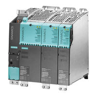
Liquid-cooled chassis power units
Brand:
Siemens
| Category:
Portable Generator
| Size: 18.72 MB
Table of Contents
Preface
5
Table of Contents
9
1 Fundamental Safety Instructions
15
General Safety Instructions
15
Safety Instructions for Electromagnetic Fields (EMF)
19
Handling Electrostatic Sensitive Devices (ESD)
19
Industrial Security
20
Residual Risks of Power Drive Systems
21
2 System Overview
23
The SINAMICS Range of Drives
23
SINAMICS S120 Drive System
27
Technical Specifications
30
Standards
33
Basic Structure of a Drive System with Liquid-Cooled SINAMICS S120
36
Structure of a Drive System with Liquid-Cooled SINAMICS S120 and Power Module
36
Structure of a Drive System with Liquid-Cooled SINAMICS S120 and Regulated Infeed
37
Structure of a Drive System with Liquid-Cooled SINAMICS S120 and Unregulated Infeed
38
3 Line-Side Power Components
39
Line Reactors for Power Modules
39
Description
39
Safety Information
39
Dimension Drawing
41
Technical Data
42
Line Reactors for Basic Line Modules
43
Description
43
Safety Information
43
Dimension Drawing
45
Technical Data
47
Active Interface Modules, Air-Cooled
48
Description
48
Safety Information
49
Interface Description
51
Overview
51
Connection Example
53
Line/Load Connection
55
DRIVE-Cliq Interface X500
55
X530 Neutral Point Grounding
56
X609 Terminal Strip
57
Meaning of the LED on the Voltage Sensing Module (VSM) in the Active Interface
58
Module
58
Dimension Drawing
59
Electrical Connection
61
Technical Data
65
Derating Factors as a Function of Installation Altitude and Ambient Temperature
67
Active Interface Modules, Liquid-Cooled
68
Description
68
Safety Information
69
Interface Description
71
Overview
71
Connection Example
73
Line/Load Connection
75
DRIVE-Cliq Interface X500
75
X530 Neutral Point Grounding
76
X609 Terminal Strip
77
X1 Temperature Sensor Connection at the Filter Reactor
77
Meaning of the LED on the Voltage Sensing Module (VSM) in the Active Interface
78
Module
78
Dimension Drawing
79
Installation
81
Notes on Installation in a Control Cabinet
82
Cooling Circuit Connections
92
Electrical Connection
94
Technical Data
98
Derating Factors as a Function of Coolant Temperature
102
Derating Factors as a Function of the Ambient Temperature
103
Derating Factors as a Function of Installation Altitude
104
Parameterization
106
4 Power Modules
107
Description
107
Safety Information
109
Interface Description
112
Overview
112
Connection Example
114
Line/DC Link/Motor Connection
115
X9 Terminal Strip
115
X41 EP Terminal / Temperature Sensor Connection
116
X42 Terminal Strip
117
X46 Brake Control and Monitoring
118
DRIVE-Cliq Interfaces X400, X401, X402
118
Cooling Circuit Connections
119
Meaning of the Leds on the Control Interface Module in the Power Module
120
Dimension Drawing
121
Installation
123
Electrical Connection
125
Technical Specifications
127
Overload Capability
128
Derating Factors as a Function of Coolant Temperature
130
Derating Factors as a Function of the Ambient Temperature
131
Derating Factors as a Function of Installation Altitude
132
Current Derating as a Function of the Pulse Frequency
134
5 Line Modules
135
Introduction
135
Basic Line Modules
136
Description
136
Safety Information
138
Interface Description
141
Overview
141
Connection Example
143
Line/Load Connection
144
X9 Terminal Strip
144
X41 EP Terminal / Temperature Sensor Connection
145
X42 Terminal Strip
146
DRIVE-Cliq Interfaces X400, X401, X402
147
Cooling Circuit Connections
147
Meaning of the Leds on the Control Interface Module in the Basic Line Module
148
Dimension Drawing
149
Installation
151
Electrical Connection
153
Technical Specifications
155
Derating Factors as a Function of Coolant Temperature
159
Derating Factors as a Function of the Ambient Temperature
160
Derating Factors as a Function of Installation Altitude
161
Active Line Modules
163
Description
163
Safety Information
166
Interface Description
169
Overview
169
Connection Example
172
Line/Load Connection
173
X9 Terminal Strip
173
X41 EP Terminal / Temperature Sensor Connection
174
X42 Terminal Strip
176
DRIVE-Cliq Interfaces X400, X401, X402
176
Cooling Circuit Connections
177
Meaning of the Leds on the Control Interface Module in the Active Line Module
178
Dimension Drawing
179
Installation
183
Technical Specifications
186
Derating Factors as a Function of Coolant Temperature
194
Derating Factors as a Function of the Ambient Temperature
195
Derating Factors as a Function of Installation Altitude
196
6 Motor Modules
199
Description
199
Safety Information
200
Interface Description
203
Overview
203
Connection Example
207
DC Link/Motor Connection
208
X9 Terminal Strip
208
X41 EP Terminal / Temperature Sensor Connection
209
X42 Terminal Strip
211
X46 Brake Control and Monitoring
211
DRIVE-Cliq Interfaces X400, X401, X402
212
Cooling Circuit Connections
212
Meaning of the Leds on the Control Interface Module in the Motor Module
213
Dimension Drawing
214
Installation
219
Technical Specifications
222
Overload Capability
233
Derating Factors
235
Derating Factors as a Function of Coolant Temperature
235
Derating Factors as a Function of the Ambient Temperature
236
Derating Factors as a Function of Installation Altitude
237
Current Derating as a Function of the Pulse Frequency
238
Parallel Connection of Motor Modules
241
7 Motor-Side Power Components
243
Sine-Wave Filter
243
Description
243
Safety Information
244
Dimension Drawing
246
Technical Data
248
Motor Reactors
249
Description
249
Safety Information
249
Dimension Drawing
251
Technical Data
254
DV/Dt Filter Plus Voltage Peak Limiter
257
Description
257
Safety Information
259
Interface Description
261
Connecting the DV/Dt Filter Plus Voltage Peak Limiter
263
Dimension Drawing, DV/Dt Reactor
265
Dimension Drawing of the Voltage Peak Limiter
268
Technical Data
271
DV/Dt Filter Compact Plus Voltage Peak Limiter
274
Description
274
Safety Information
276
Interface Description
278
Connecting the DV/Dt Filter Compact Plus Voltage Peak Limiter
281
Dimension Drawing for DV/Dt Filter Compact Plus Voltage Peak Limiter
284
Technical Data
290
8 Cabinet Design and EMC
295
Notes
295
General
295
Safety Information
295
Directives
297
EMC-Compliant Design and Control Cabinet Configuration
298
Cabinet Installation, Vertical and Horizontal Installation
298
Mounting on Mounting Rails
298
Horizontal Installation
302
Vertical Installation
303
Housing for Air Guidance
304
Motor Connection Cover
304
Volumetric Air Flow and Fans Required
305
Coolant Connection
308
9 Cooling Circuit, Coolant Properties and Protection against Condensation
309
Cooling Circuits
310
Cooling Circuit for Aluminum Heat Sinks
313
Cooling Circuit for Stainless Steel Heat Sinks
315
Preventing Cavitation
316
Cooling Circuit Configuring Information
317
Equipotential Bonding
332
Coolant Definition
332
Coolant Properties
332
Antifreeze, Biocides, Inhibitors
335
Materials
338
Anti-Condensation Measures
339
Examples of Coolant Control
340
Connection Methods
344
Commissioning
345
Service
347
10 Maintenance and Servicing
349
Chapter Content
349
Maintenance
350
Servicing
352
Replacing Components
353
Safety Information
353
Messages after Replacement of DRIVE-Cliq Components
353
Mounting Equipment for Power Units
354
Replacing the Control Interface Module, Power Module, Frame Size FL
356
Replacing the Control Interface Module, Power Module, Frame Size GL
358
Replacing the Control Interface Module, Motor Module, Frame Size FXL
360
Replacing the Control Interface Module, Active Line Module and Motor Module, Frame Size GXL
363
Replacing the Control Interface Module, Active Line Module and Motor Module, Frame Size HXL
365
Replacing the Control Interface Module, Active Line Module and Motor Module, Frame Size JXL
367
Replacing the Control Interface Module, Basic Line Module, Frame Size FBL
370
Replacing the Control Interface Module, Basic Line Module, Frame Size GBL
372
Replacing the Electronic Fan, Power Module, Frame Size FL
375
Replacing the Electronic Fan, Power Module, Frame Size GL
378
Replacing the Electronic Fan, Motor Module, Frame Size FXL
381
Replacing the Electronic Fan, Active Line Module, and Motor Module, Frame Size GXL
384
Replacing the Electronic Fan, Active Line Module, and Motor Module, Frame Size HXL
387
Replacing the Electronic Fan, Active Line Module, and Motor Module, Frame Size JXL
390
Replacing the Electronic Fan, Basic Line Module, Frame Size FBL
393
Replacing the Electronic Fan, Basic Line Module, Frame Size GBL
396
Replacing the Fan, Active Interface Module, Frame Size GI
399
Replacing the Fan, Active Interface Module, Frame Size HI
401
Forming the DC Link Capacitors
403
Appendix
407
Cable Lugs
407
List of Abbreviations
408
Index
413
Advertisement
Advertisement
Related Products
Siemens Simantic ET200SP
Siemens Simantic S7-1500
Siemens Simantic ET 200S
Siemens SIMATIC PN coupler
Siemens SIMATIC NET SFP+
Siemens SIMATIC NET SCALANCE XC-200 Series
Siemens SIMATIC NET SCALANCE M874
Siemens SIMATIC NET SCALANCE XC-100
Siemens SIMATIC NETRUGGEDCOM RS900W
Siemens SIMATIC HMI KTP1000 Basic color PN
Siemens Categories
Industrial Equipment
Controller
Control Unit
Oven
Washer
More Siemens Manuals
Login
Sign In
OR
Sign in with Facebook
Sign in with Google
Upload manual
Upload from disk
Upload from URL